 "bhtooefr" (bhtooefr)
02/28/2018 at 08:45 • Filed to: owen magnetic, transmission
 3
3
 6
6|
"bhtooefr" (bhtooefr)
02/28/2018 at 08:45 • Filed to: owen magnetic, transmission | 3
| 6 |
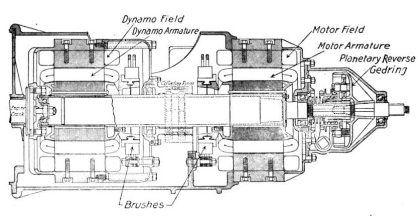
Make a !!!error: Indecipherable SUB-paragraph formatting!!! , as used in the Owen Magnetic.
Both the generator and the motor armatures are connected to the output shaft, with the generator field connected to the crankshaft (and therefore spinning at engine speed).
Weaken the dynamo field, spin up the engine, and it’ll generate less voltage and more current, going straight to the motor to get you moving in “first”.
Weaken the motor field progressively, and it’ll generate less and less torque, and operate at higher speeds, while also pulling less power off the dynamo. Meanwhile, torque from the engine to the output shaft through the dynamo’s spinning will increase.
Short the dynamo brushes in “top” gear, and then you almost get total lockup (with an 80 RPM slip, apparently), with no power transmitted to the motor (and therefore no power splitting).
(You could actually take that further, hypothetically, and pull power off of the motor and put it into the generator - something that the Toyota hybrids actually do at very high speeds with very low engine power demand, to lower engine RPM. However, that would require more complex controls that likely weren’t seen as necessary in the 1910s.)
...also, while I’ve suggested another transmission - the Honda Juno scooter’s transmission - was the first power-split transmission in a production vehicle before, and was proven wrong by the original GM Hydra-Matic having a power-split torque pathway in some gears, this is decades before the original Hydra-Matic. (And, interestingly, I think it’s actually using a similar input slipping model to the Juno and later Honda HFT hydraulic power-split transmissions, to get the effects of planetary gearing without actually having planetary gears.)
Oh, and this transmission was brushed upon on here !!!error: Indecipherable SUB-paragraph formatting!!! , but I thought I’d mention it because it’s quite neat, especially given the era.
!!! UNKNOWN CONTENT TYPE !!!
 Spanfeller is a twat
> bhtooefr
Spanfeller is a twat
> bhtooefr
02/28/2018 at 08:49 |
|
You know about Koeninseg’s freevalve thing?
It’s pneumatic; compressed air drives the valves.... why did they do it that way and not magnetic? Well, magnetic valve mechs are already patented (and the patent already expired) so it’s free to use, no way to suck money out of it.
Although... I am mostly certain that there must be a problem with using magnetic valve openers that doesn’t make them widespread today.
 Azrek
> bhtooefr
Azrek
> bhtooefr
02/28/2018 at 08:51 |
|

|
bhtooefr
> Spanfeller is a twat
02/28/2018 at 08:57 |
|
Power consumption.
Freevalve only needs to electrically modulate the air supply to the valve, where magnetic valve actuation needs to move the valve itself electrically.
Similarly, Fiat MultiAir (which is in production, you can go buy a Fiat 500 or Jeep Renegade using it today) only needs to electrically modulate oil supply to the valve.
 MasterMario - Keeper of the V8s
> Spanfeller is a twat
MasterMario - Keeper of the V8s
> Spanfeller is a twat
02/28/2018 at 09:01 |
|
I didn’t know that but thinking about it now it might have to do with failure modes. If the pneumatic ones fail it’s most likely from a leak in the system and valves simply don’t open. If the magnetic one’s fail it’s probably from a voltage spike or something wrong in the controls/wiring and that probably means actuating the valve at the wrong time and likely damaging the engine. That’s my thought anyways. Also, the open patent means less money to make. You do all the R&D, figure it out, then your competitors just reverse engineer your design.
|
Spanfeller is a twat
> bhtooefr
02/28/2018 at 09:04 |
|
Hmm... that makes a lot of sense.... also that multi air thing is quite interesting! JLR is using it on their ingenium engines
However, have you seen the Freevalve system? I love it, but it seems so complex just from looking at the patent....
|
Spanfeller is a twat
> MasterMario - Keeper of the V8s
02/28/2018 at 09:07 |
|
Yeah, you can still get a dpat on it.... but it’s obviously not the same.