 "Ike" (untitledcarshow)
05/30/2019 at 20:45 • Filed to: None
 0
0
 4
4
 "Ike" (untitledcarshow)
05/30/2019 at 20:45 • Filed to: None |  0 0
|  4 4 |
Not just anybody, I need some one who can read wiring diagrams.
Trying to figure out quad 4’s wiring. I have all the things hooked up to the motor, now I’m trying to figure out what needs power .
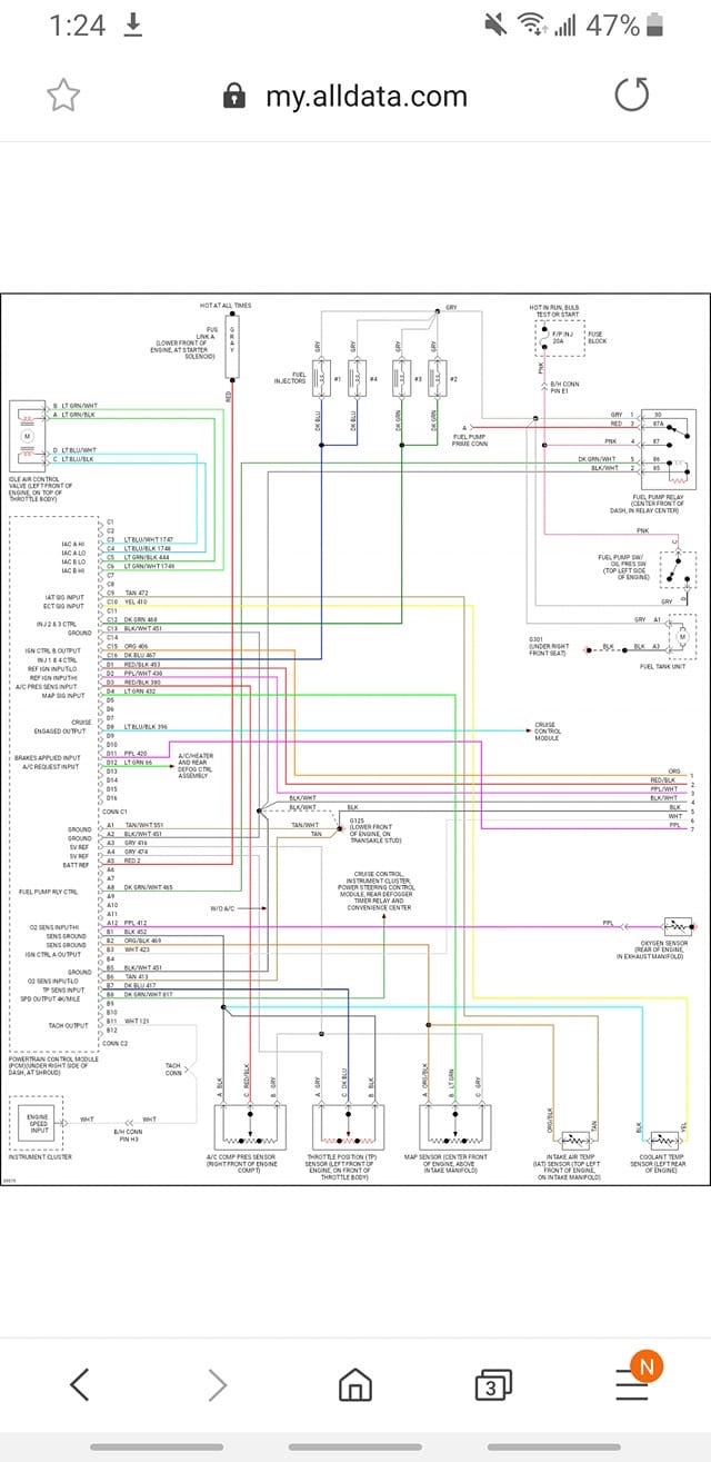
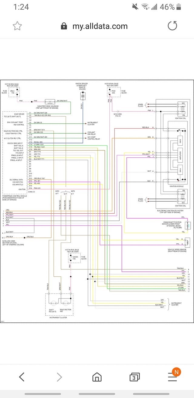
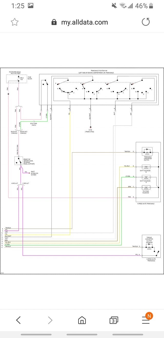
Here’s the diagrams I’m working with
 Future Heap Owner
> Ike
05/30/2019 at 21:01 |
|
These are pretty low-res screenshots; can you link to the datasheet?
Also I can’t really dig into this for another four to five hours, but if nobody has by then, I’ll take a close look.
 Ike
> Future Heap Owner
05/30/2019 at 21:04 |
|
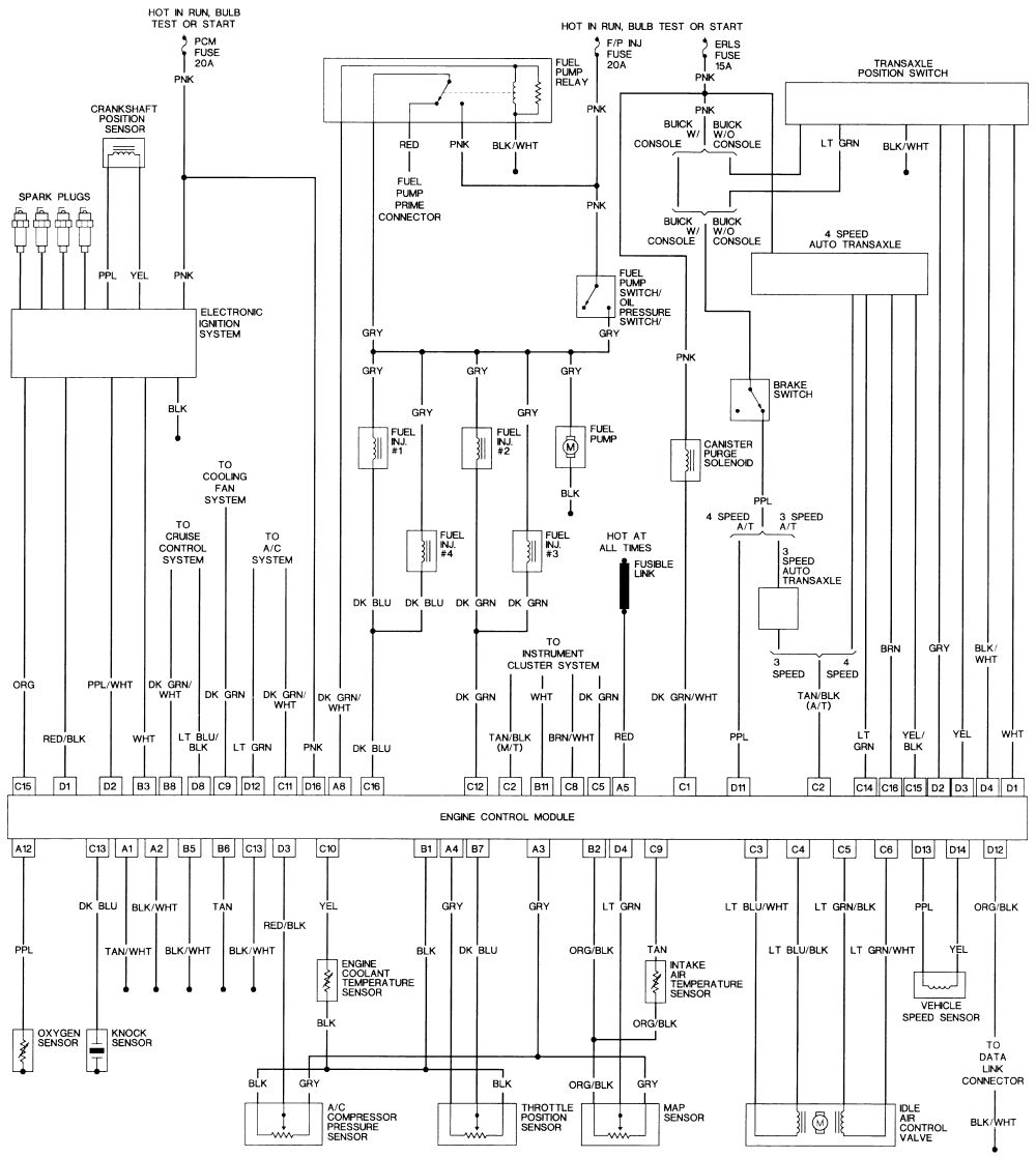
Those are what I was able to get from a fellow on the forums, I have these as well that I was able to dig up or 100% on them tbh (also thank you)
 Urambo Tauro
> Ike
05/30/2019 at 22:26 |
|
I have all the things hooked up to the motor, now I’m trying to figure out what needs power .
Everything marked “hot” needs battery power (+) , fused or switched in accordance with what the diagram says .
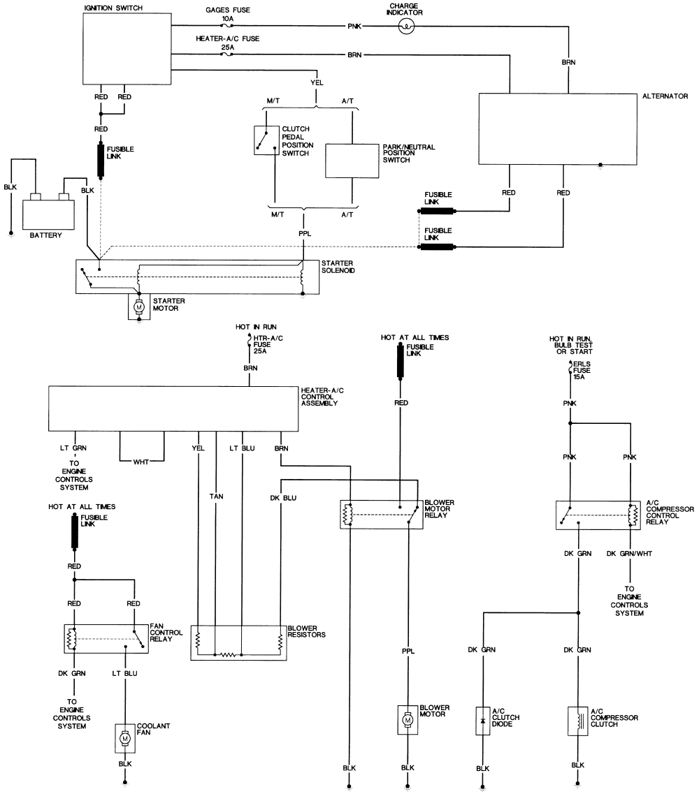
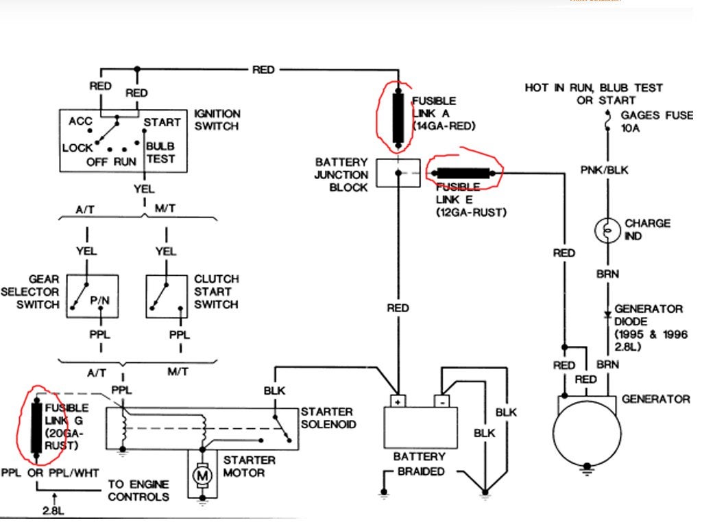
I’m having a hard time reading these , but it looks like the pink wire in the first diagram needs to g o to your fuse block, where it can be protected by a 20A fuse, and only have voltage when the key is turned forward “hot in run, bulb test, or start”. I also see a fuse link on that page that needs to go to the starter solenoid where your + battery cable attaches. That one’s “hot at all times”, meaning that there is always voltage on that circuit ( as long as the battery is hooked up) .
 Future Heap Owner
> Ike
05/31/2019 at 02:06 |
|
These are much easier to read; I have a really hard time making things out on the other diagram, so I’m not even gonna try.
Urambo Tauro is correct about how to tell what needs power. From these diagrams, it looks like that means:
red wire to engine control module (fusible link), hot always;
black wire to starter solenoid (no fuse or link), hot always; (Also, the last diagram references a purple wire from the starter solenoid to “engine controls” with a fusible link, which the previous set of diagrams does not show.)
red wires to ignition switch (fusible link), hot always;
red wires to alternator (fusible link), hot always;
pink wire to ignition system & engine control module (with a 20A ‘PCM’ fuse), hot when key turned;
pink wire to fuel pump switch & fuel pump relay (20A ‘F/P INJ’ fuse), hot when key turned;
That’s probably all you need to get things running, but these further hot wires are also mentioned:
pink or pink & black wire to charge indicator and then to alternator (10A ‘GAGES’ fuse), hot when key turned;
pink wire to canister purge solenoid, transaxle, and possibly to transaxle position switch (15A ‘ERLS’ fuse), hot when key turned;
red wire to blower motor relay (fusible link), hot always;
red wires to fan control relay (fusible link), hot always;
pink wires to A/C compressor control relay (15A ‘ERLS’ fuse), hot when key turned (this is only in the first set of diagrams in your comment, not the last one).
Note that some of the hot wires that are distinct in the diagram may only be one in reality (like all the pink wires from the ERLS fuse), and exactly how the fuses get their power is unclear to me from the diagrams.