 "sony1492" (sony1492)
06/12/2018 at 18:16 ē Filed to: Lexus
 3
3
 4
4
 "sony1492" (sony1492)
06/12/2018 at 18:16 ē Filed to: Lexus |  3 3
|  4 4 |
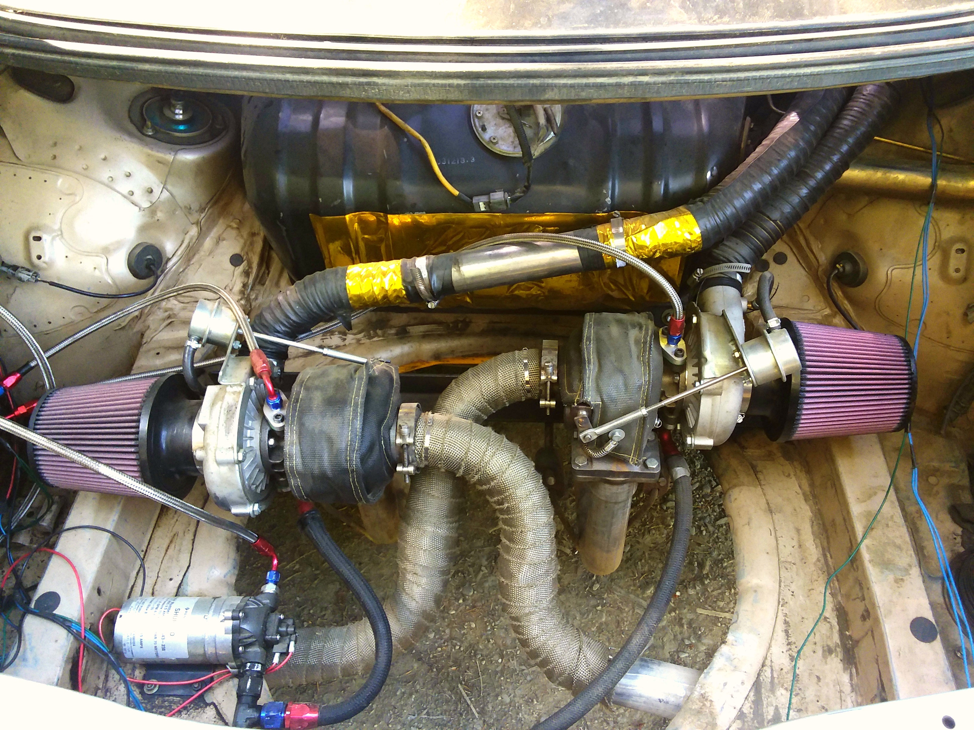
Trying to finalize my turbo charge pipe situation, its currently 16.4ft 2" and 4ft 3" pipe, if that dosent sound efficient its because its not. I need to figure out what sizes to use and Iím not sure how velocity figures in. Ideas are appreciated.

Two 2" pipes totaling 16.4ft Yíing into 4ft of 3" pipe that connects to the throttle body.(rough measurements) The total volume is 957in cubed. I want to replace the hokey flexible ducting with steel and while Iím at it make it spool faster (without choking the motor).

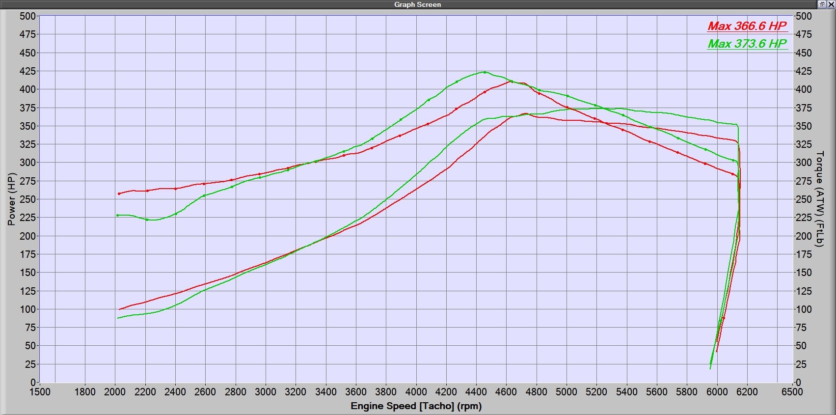
On the dyno in 5th gear the car made at least 1psi from 2000 and that climbed until about 3600 where the turbo began to really spool, Peaking 7psi at 4400.
I want to connect the two turbos earlier and run a single charge pipe through the car, so it would be about 3-4ft 2" pipe then 8-10ft of 2.25, 2.5, 2.75, or 3" pipe. I donít know what size to pick.
Due to the turbos sitting so far back the exhaust gasses cool and the turbos are less efficient, so the motor runs at atmospheric pressure until about 3500rpm.(depending on gear) Iím afraid if I choke the motor by using a charge pipe thatís too small it will take even longer to spool. I just canít imagine a 4.0 v8 being happy pulling air through a 2.5Ē straw, but on the other hand it seems unlikely that youíd pressurized 10ft of 3" and still have good pressure.
What calculations should I be doing? How does velocity and Cfm play into all this? Any ideas
 Montalvo
> sony1492
06/12/2018 at 20:49 |
|
Never had to†go through this myself but I would say that the pipe needs to be sized according to the turbos. There will be some limit that the turbos can effectively compress. The rate at which the turbos can compress will give you your CFM. The velocity will then depend on the cross sectional area and how well the air flows (laminar/turbulant,†friction, bends/connections) The pipes would need to be sized to take into account these losses and variables. Not really sure how to go about it with just 5 min of thought but I have no doubt someone on here knows exactly how to do it.
 diplodicus forgot his password
> sony1492
06/12/2018 at 21:59 |
|
http://www.pipeflowcalculations.net/pipediameter.xhtml have you tried a calculator? Doesnít have a length, but could give you some idea.
 sony1492
> diplodicus forgot his password
06/12/2018 at 23:51 |
|
That calculator requires that you pay to use it, but itís got me on the right track.
 sony1492
> Montalvo
06/13/2018 at 09:57 |
|
For cfm I calculated what the motor pulls at 6000rpm and 85% volumetric efficiency, this made 360cfm stock. Then the same calculation is done but factoring in 9psi(my goal) to get 580cfm. I can divide either number by 2 to see how much air is passing through each turbo. The velocity through various pipe sizes will tell me my lag time and I can compare it to stock.
Now i need to figure out how much air will fill a vacuum traveling through a given pipe size. This will tell me if the motor will be restricted before the turbo comes online because I can compare how much air atmospheric pressure will move and how much the motor injests.
†Iím not sure if what sort of velocity I should want. I imagine there will be problems at very high velocities, currently itís around 40-50m/s but depending on the pipe setup it can get to 80m/s(with a ridiculous size). Stock the car was closer to 30m/s pulling 360cfm through a 3in pipe