 "Urambo Tauro" (urambotauro)
04/10/2017 at 18:00 • Filed to: 41TE, Automatic Transmission, Rebuild, Blog
 4
4
 8
8|
"Urambo Tauro" (urambotauro)
04/10/2017 at 18:00 • Filed to: 41TE, Automatic Transmission, Rebuild, Blog | 4
| 8 |
Prepare your body...
Before closing up the transmission, we must first assemble the main hydraulics. A few changes are being made to this valve body, and if you’ve ever wondered just what exactly a “shift kit” consists of, you’re about to find out.
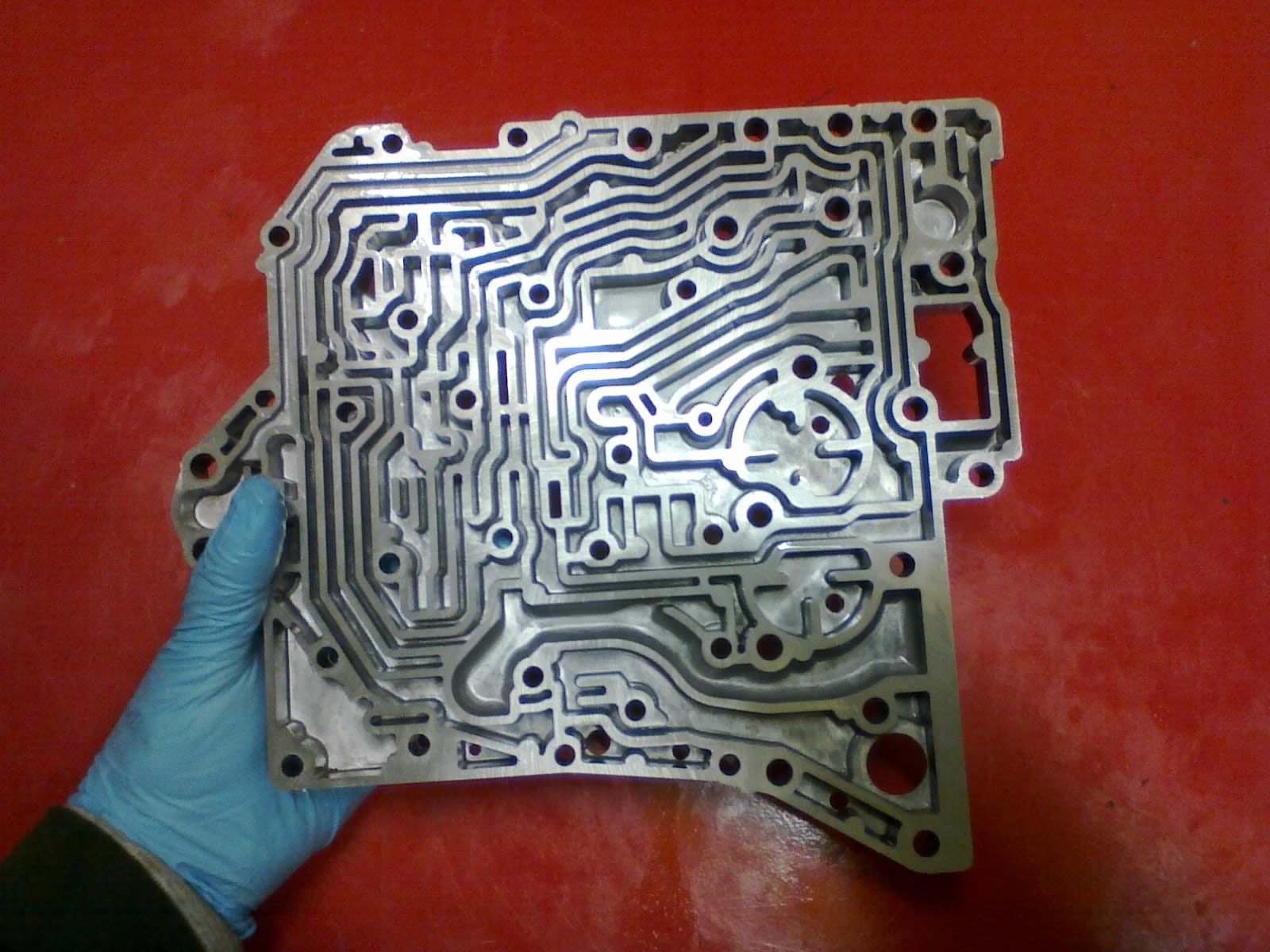
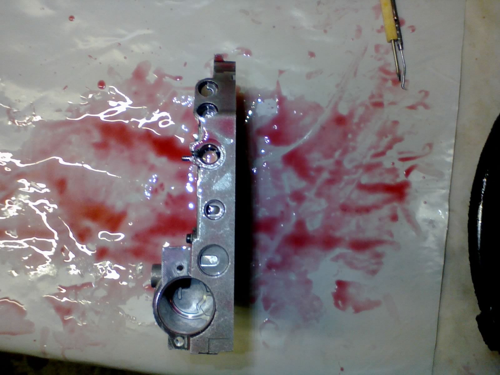
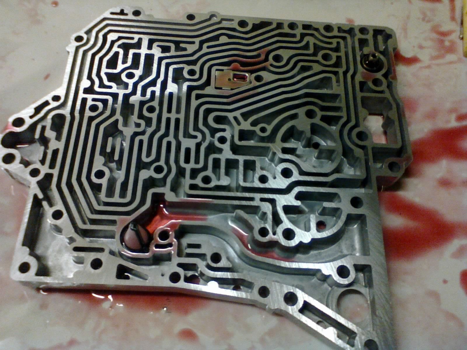
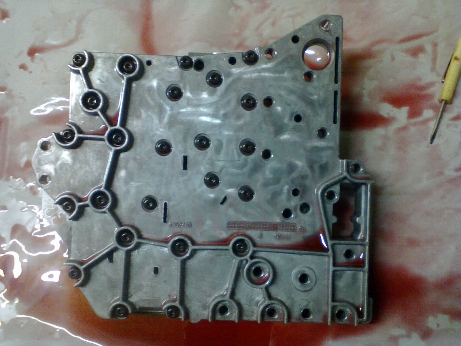
The main valve body houses all of these valves.
I never did find out what this valve was called, but it was one of the easier ones to reassemble. Just one valve, one spring, and a retainer.
Regulator valve
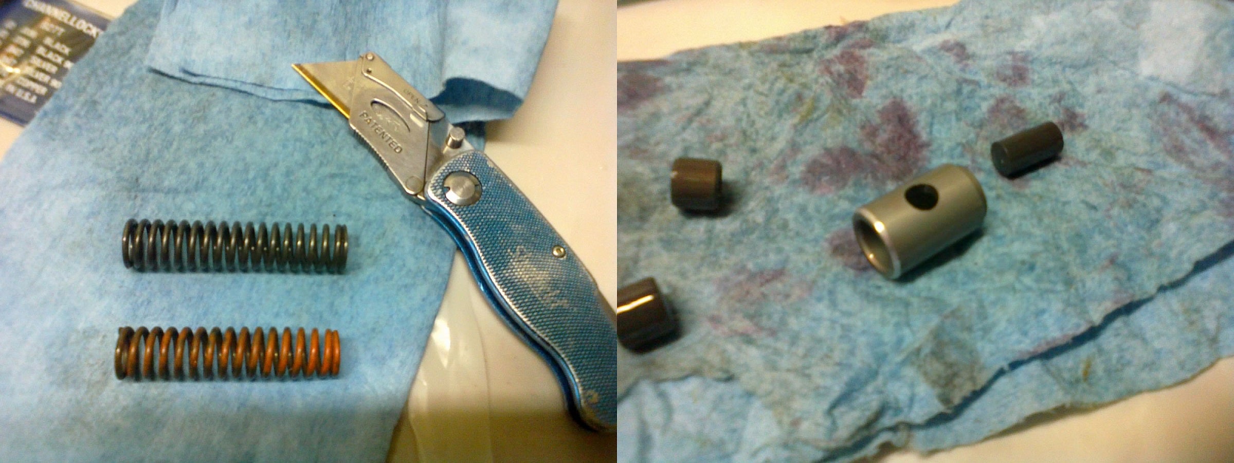
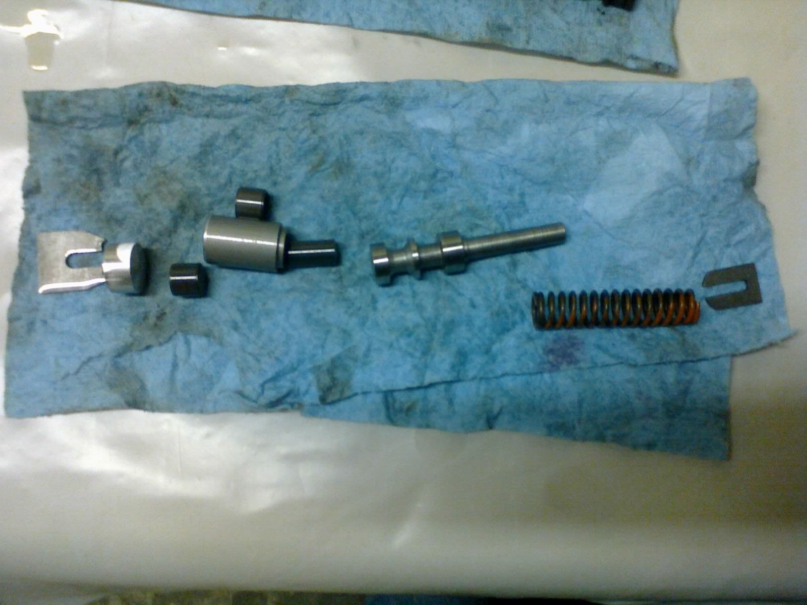
LEFT: As part of the shift kit being installed in this unit, this orange spring replaces the stock one in the regulator valve. Doesn’t look too much different, does it? RIGHT: This bushing has a shiny edge on it because the kit calls for a chamfer to be ground into it. This is to help prevent the sharp edge from hanging up in the bore.
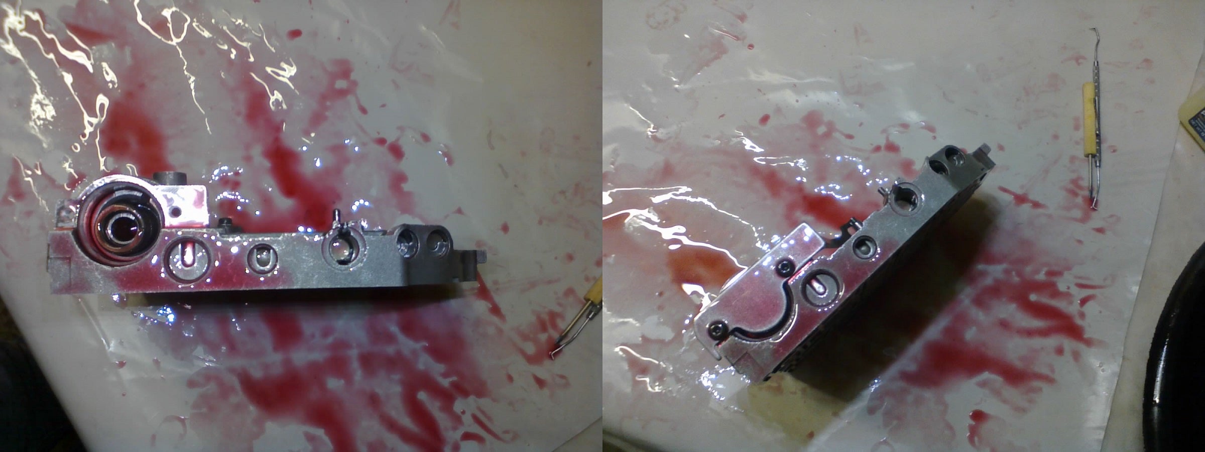
Solenoid switch valve
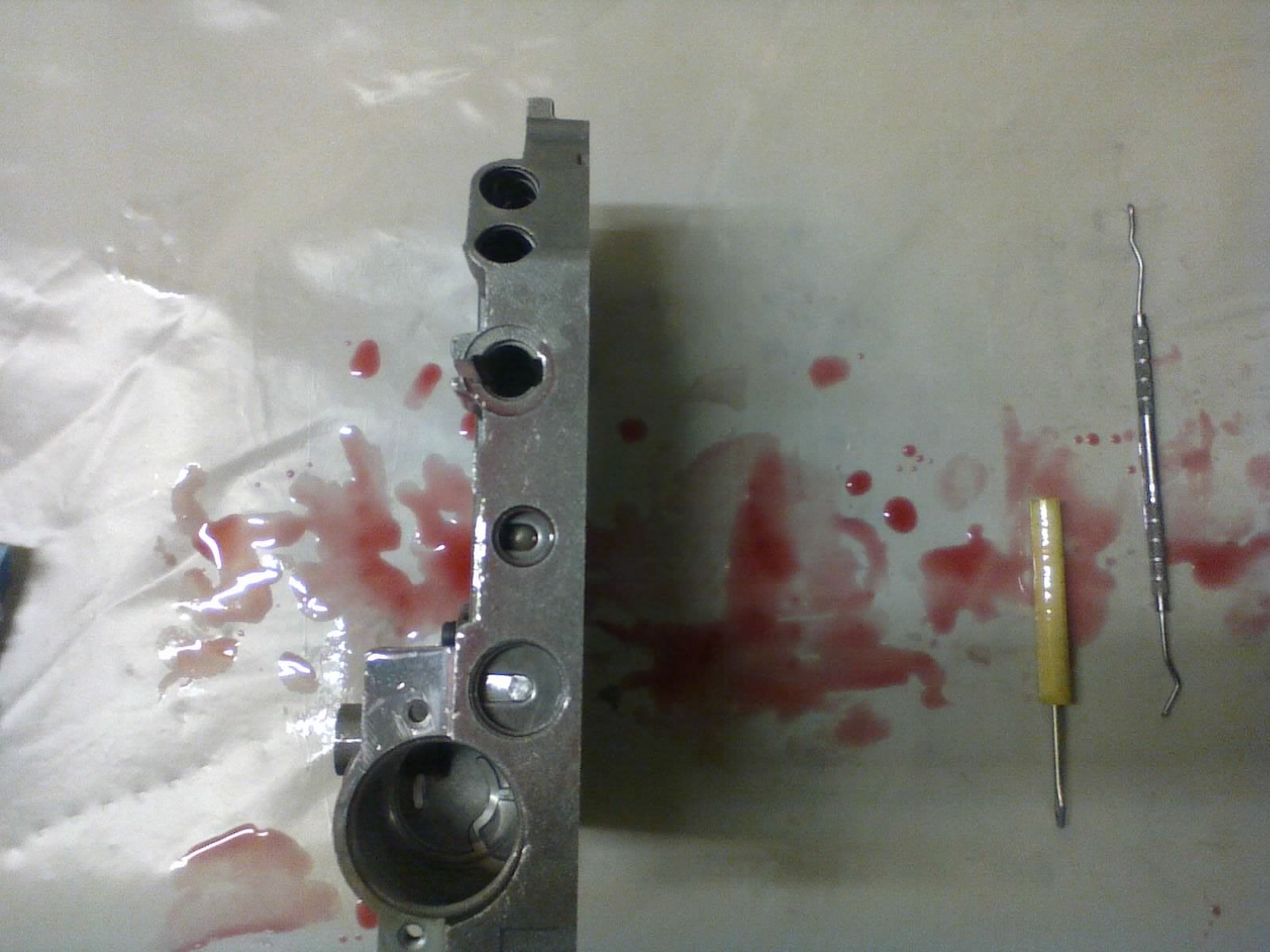
Regulator valve and solenoid switch valve locked into their bores
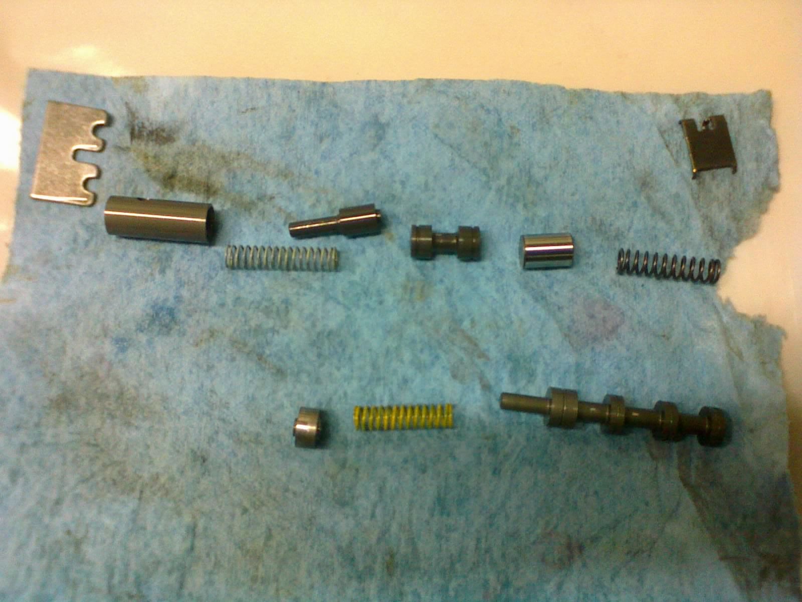
TOP: torque converter clutch valve. BOTTOM: T/C control valve. Both valves are held in by the large retainer on the top left. The one on the top right retains part of the TC clutch valve, and is installed before the rest of that valve is assembled.
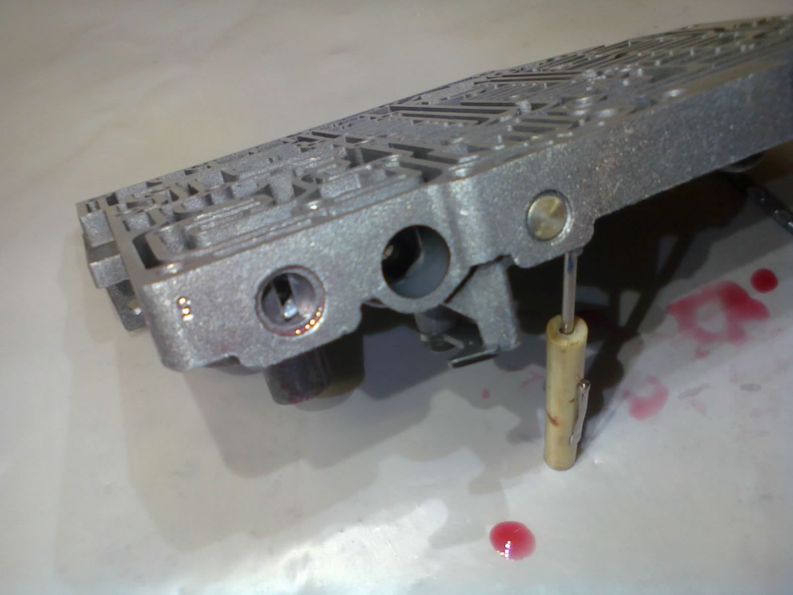
Those valves are installed into the valve body, along with the manual valve. Part of the manual valve bore has a slit in the top, out of which a small rod stick out perpendicular to the valve. More on that in the next post.
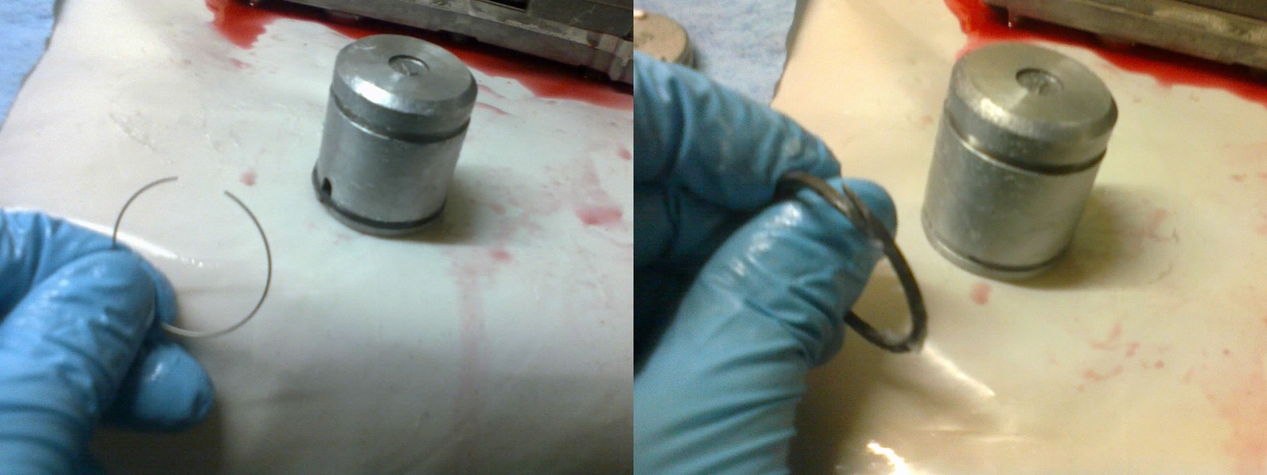
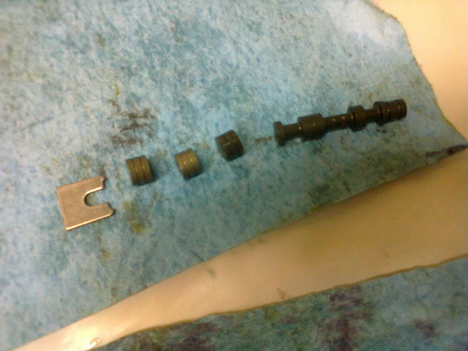
Another part of the shift kit involves slipping this tiny little wire into the 2-4 piston groove before adding the scarf-cut seal ring. Though the piston has two grooves, only the one near the closed end of the piston needs the expander ring under the seal.
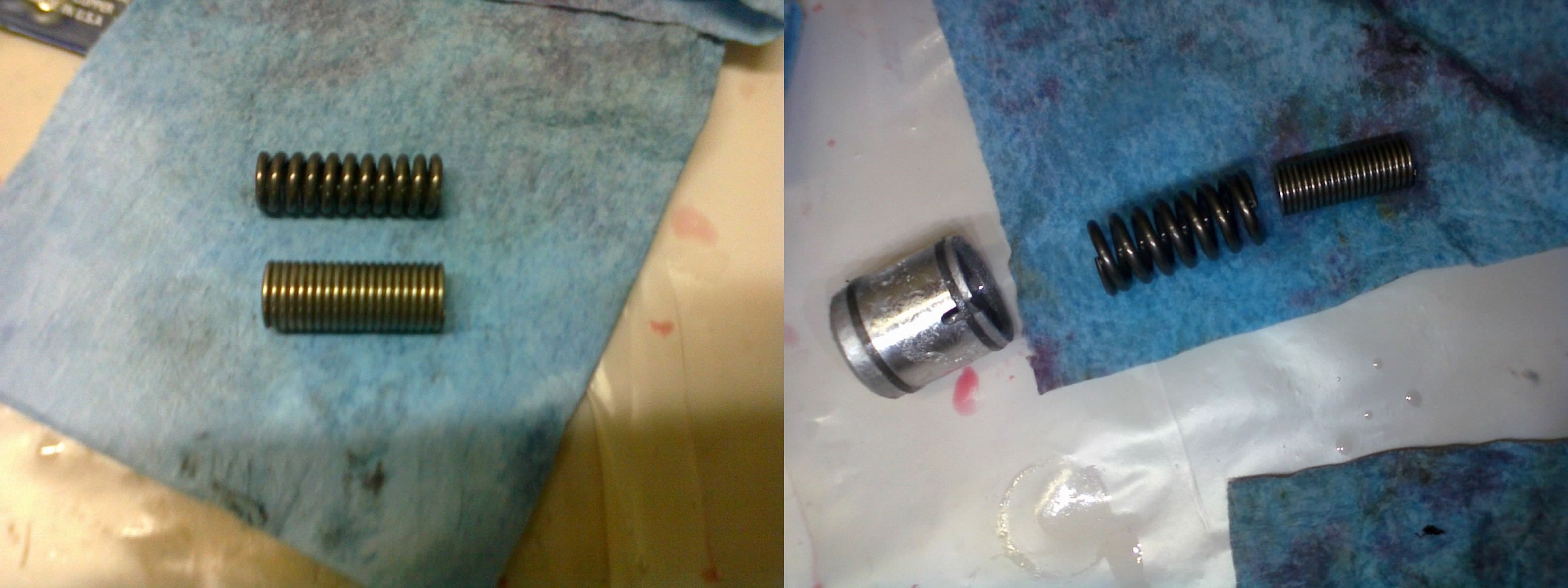
LEFT: The spring on the top gets replaced by this spring-like spacer on the bottom. RIGHT: The spacer goes inside this larger spring, and they both slip inside the 2-4 accumulator piston.
The 2-4 accumulator piston, spring, and spacer go into their bore, and are covered by this plate. The plate also retains a spring-arm with a roller that will engage the rooster comb. More on that in the next post.
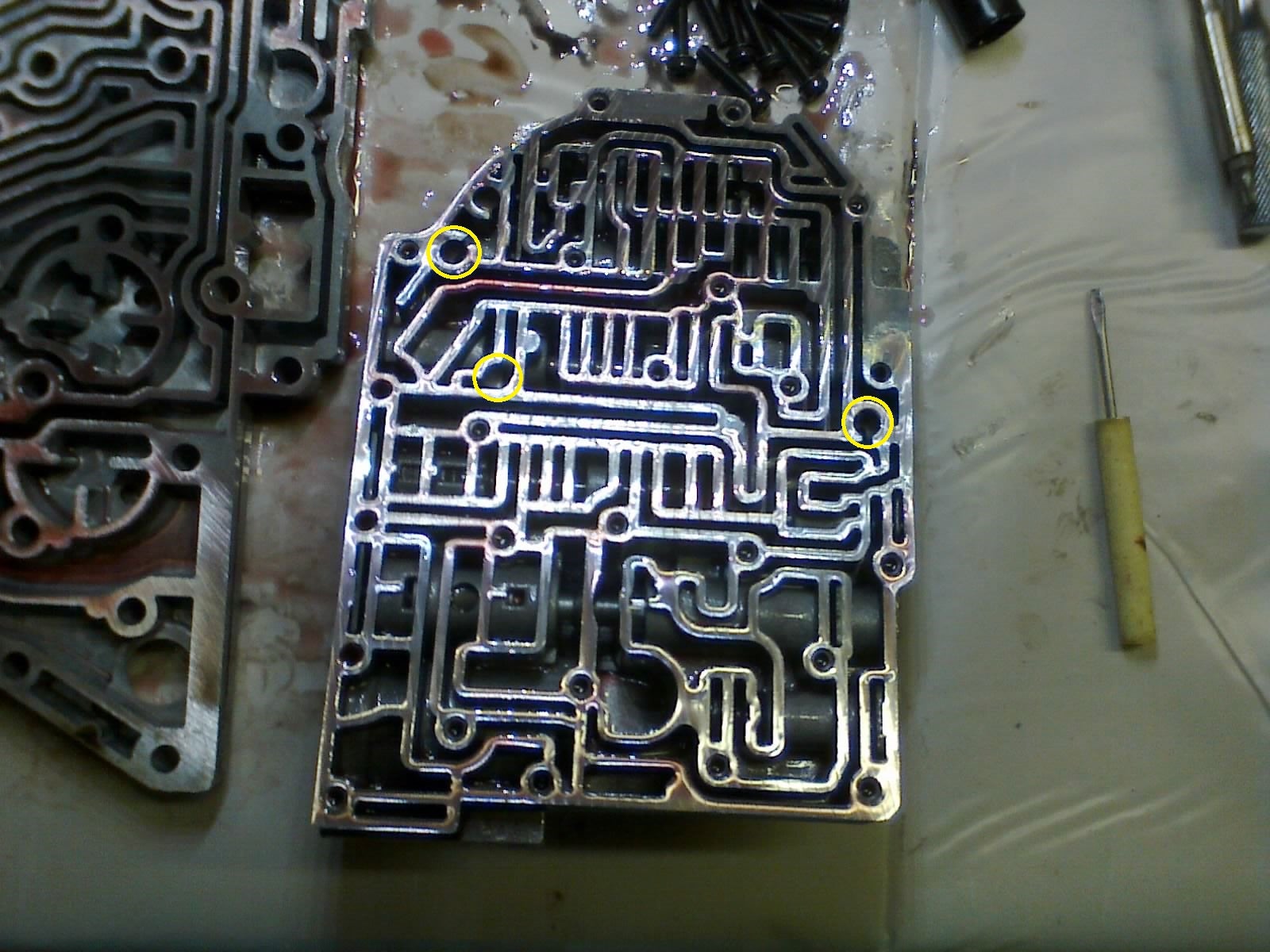
I forgot to take a clean version of this pic, but here is a reminder of where the check-balls go before we attach the transfer plate
The thermal valve (top center) gets reinstalled, and the spring-loaded orifice (upper right) does too, with a new O-ring. A new screen also goes in. This one is cone-shaped to accommodate different valve bodies, but is backwards-compatible for this application, too.
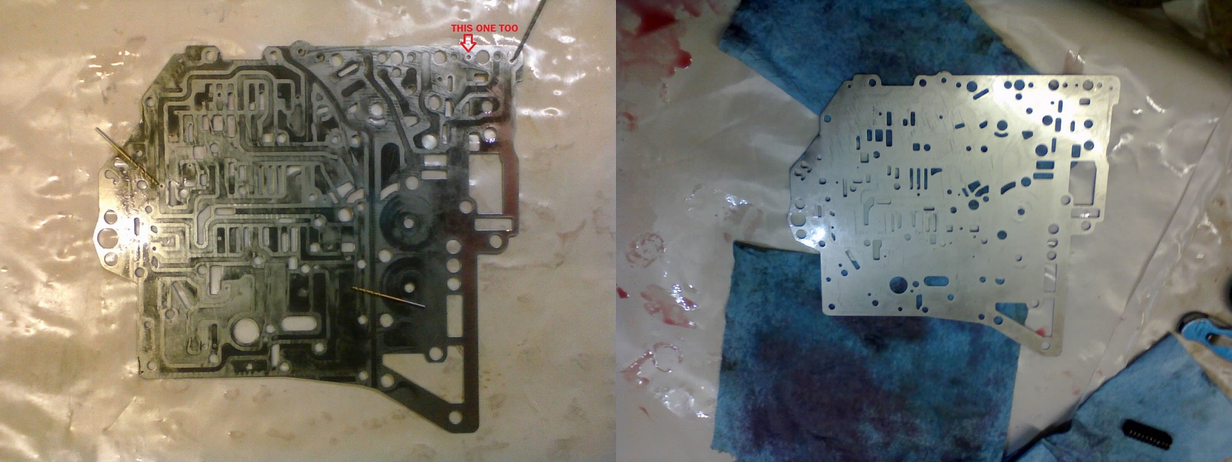
Shift kits often include specific drill bits for enlarging certain feed holes, but in this case, it only came with one. Fortunately, I had a big set of drill bits that included the oddball number sizes that the kit called for. After drilling, the holes get deburred and the plate can be cleaned.
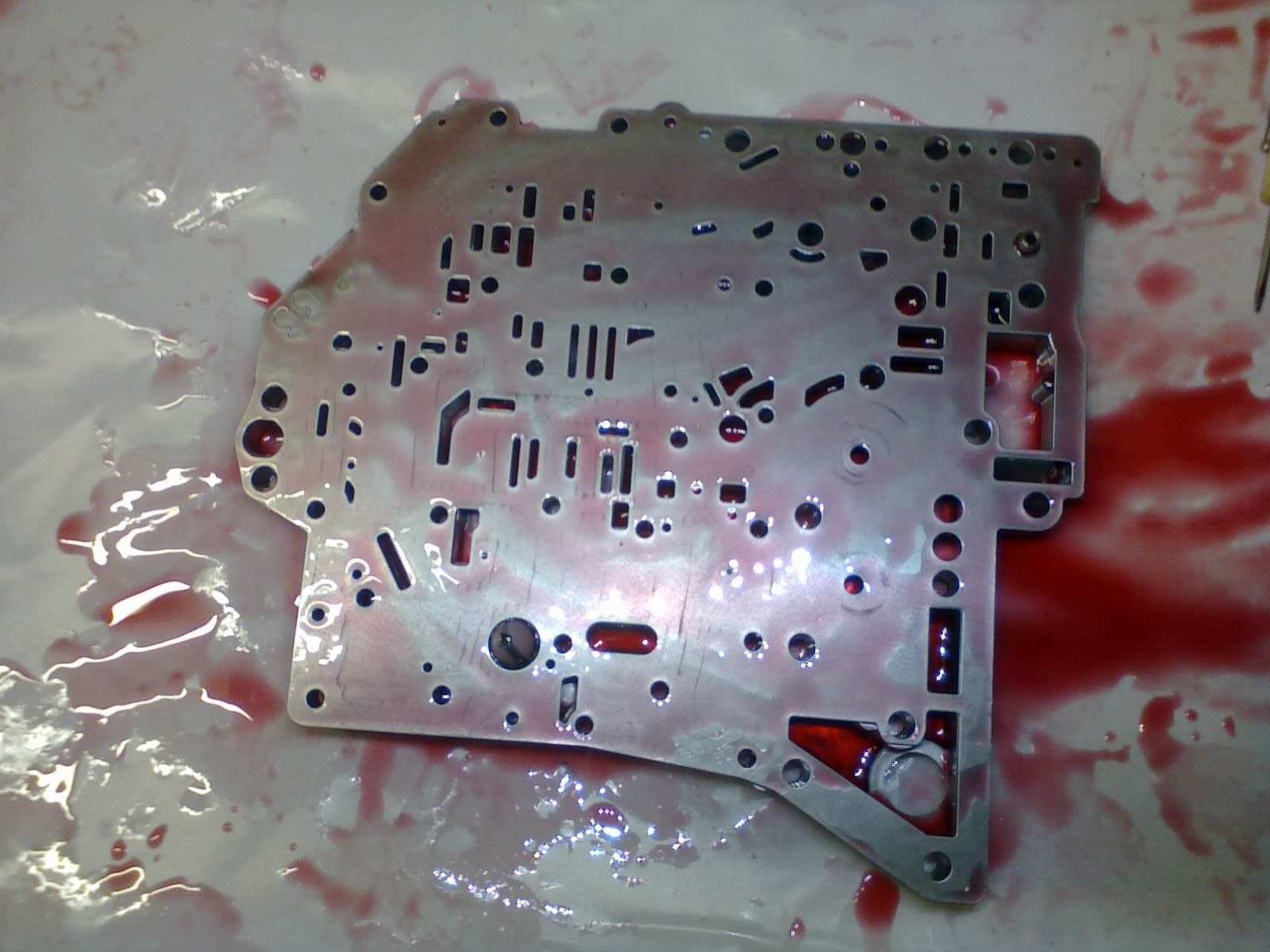
The separator plate gets laid over the transfer plate (you can see the screen cone and spring-loaded orifice poking through). Now, we carefully hold the plates together as we flip them upside-down...
...and lay them both right on top of the main valve body. These torx bolts clamp the transfer plate to the main valve body, sandwiching the separator plate in-between and trapping the check-balls inside their passages.
No gaskets, apparently. I thought that was a little strange, but I kinda like not having to scrape gasket material from all those worm-tracks.
We’ll resume assembly of the valve body in the next post. !!!error: Indecipherable SUB-paragraph formatting!!!
 TheHondaBro
> Urambo Tauro
TheHondaBro
> Urambo Tauro
04/10/2017 at 18:08 |
|
Who the fuck did you murder?!?!
 Future next gen S2000 owner
> Urambo Tauro
Future next gen S2000 owner
> Urambo Tauro
04/10/2017 at 18:11 |
|

|
Urambo Tauro
> TheHondaBro
04/10/2017 at 18:20 |
|
Just some random pedestrian. Fuggedaboutit.
|
Urambo Tauro
> Future next gen S2000 owner
04/10/2017 at 18:22 |
|
LOL
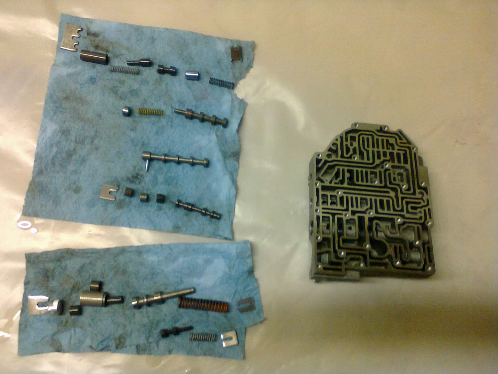
This is, without a doubt, the scariest part of the whole job. WAY too many parts to remember where they all go. I took lots of pictures, but laying everything out in order and not disturbing them until I was ready to reassemble works great, too.
Those check balls add a whole ’nother level to this. Most of the transmission can be carefully taken apart and put back together just the way you found it. But if you unbolt the valve body and flip it over, those check balls can fall out before you get a chance to see which holes they came out of.
|
Future next gen S2000 owner
> Urambo Tauro
04/10/2017 at 18:33 |
|
There is a balls in the wrong hole joke to be made.......
 TahoeSTi
> Urambo Tauro
TahoeSTi
> Urambo Tauro
04/10/2017 at 18:45 |
|
I’m afraid to ask how the shift kit works.. ...seems more complicated then my short throw shifter.
|
Urambo Tauro
> TahoeSTi
04/10/2017 at 18:58 |
|
TBH, I didn’t take the time to understand each hydraulic circuit. These mods were all done on faith that they would make it shift... “better”. Whatever that means.
I think the springs might be for dampening the shifts. Sometimes you take them out, sometimes you replace them with different ones (identified by color). I believe this firms up the shifts.
Enlarging some of the feed holes allows accumulators to fill up with fluid faster. This was particularly noticeable on my Thunderbird’s 4R70W, where a hole for the reverse servo was drilled a little bigger, which nearly eliminated the one-second delay between shifting into Reverse and feeling it engage.
 Bultaco's JMOD TownCar drives his pa to drinkin
> Urambo Tauro
Bultaco's JMOD TownCar drives his pa to drinkin
> Urambo Tauro
04/11/2017 at 01:18 |
|
In Jerry we trust.