 by "Cé hé sin" (michael-m-mouse)
Published 12/04/2017 at 14:35
by "Cé hé sin" (michael-m-mouse)
Published 12/04/2017 at 14:35
Tags: Fell mechanical locomotive
STARS: 8
We’ve seen many ways of varying your gears to suit the circumstances. You can have a simple manual gearbox, or several of them in series to give you dozens of speeds if you want them. You can have traditional belt-and-pulley CVTs or you can have something like Toyota’s eCVT which uses a motor/generator to vary ratios. You can have conventional automatics with a torque converter, clutches and brake bands or you can have hydrodynamic transmissions which switch between torque converters and fluid couplings.
What we haven’t seen is a transmission which uses multiple engines. You what? Multiple engines. Yes, really.
Meet the Fell Diesel Mechanical Locomotive or to give it its official title, British Rail class 10100.
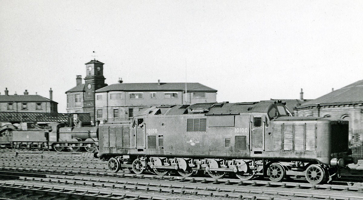
As we can see from the spoked wheels and external conrods, this is a diesel designed and built by people more accustomed to steam. The design dates back to 1949, a time when railways in the UK were considering moving on from kettles to chugs - or in English, transitioning from steam to diesel. This brought with it a challenge. Unlike steam or electric traction, a diesel needs a starting mechanism and a system of variable gears. Nowadays both of these needs are met with electric drive (engine/alternator/motors) but back then diesel electrics were found to be heavy and troublesome. The London, Scottish and Midland Railway and Lt Col LFR Fell (this was just after WW2 and there were Lt Cols everywhere) came up with something completely different. The Fell loco used six engines, four fluid couplings, three differentials and two superchargers (because superchargers are always good) to form a four speed mechanical drive loco which produced its maximum torque at low speeds.
Using all these engines might sound strange, but there was method behind it. Several small engines rather than one huge one meant a lighter frame and in the event of trouble engines could be swapped in and out relatively easily. You also had the benefit of redundancy because you could still proceed with one or more engines out of action. So, how did it all work?
First of all we need to realise that a differential can be used to provide a reduction gear. If you take a car, plant one of the driving wheels up on an axle stand and put it in gear you’ll find that the airborne wheel spins while the grounded one stays still. This is due to the differential, a clever device which allows two driven wheels to turn at different speeds. The average speed of the wheels stays the same so if one speeds up the other must necessarily slow down and vice versa. Prevent one from turning and the other will turn at twice its usual speed. This however goes both ways. Prevent one wheel from turning (a one way clutch will do), turn the other and what would have been the input now turns at half speed. Turn the other wheel at the same speed as the first and the input (as used to be) now turns at full speed. Now we’ve got the makings of a two speed transmission. The Fell loco used a pair of engines at each end with a differential between each pair. Each engine was attached to one side of the differential by a fluid coupling, while a one way clutch prevented unwanted rotation. If one of the fluid couplings was engaged the engine would turn the diff, the one way clutch prevented the other side of the diff from turning so the remaining element turned at half the speed of the engine. Next the second coupling is engaged and with both sides of the diff rotating the output is now at full speed. The other end of the loco had exactly the same going on. In the middle was found a third, central differential which operated using the outputs of the other two. The options then were low speed from one end only (first gear), high speed from one end only or low from each end (second gear), high speed from one end and low from the other (third gear) and high speed from each end (fourth gear). To start off then the driver just had to engage one engine (in principle any one of the four would do) and apply power. When more speed was called for he engaged a second engine (again any one would do) and so on.
That accounts for four of the six engines. What about the other two? They drove the pair of superchargers which supplied both themselves and the traction engines. The unusual thing was that the auxiliary engines and their respective blowers ran at a constant speed regardless of the demands of the main engines. On starting off then the first gear engine was supercharged to within an inch of its life. As speed increased and more engines and more revs were applied without any corresponding increase in blower output the level of supercharging decreased and so the power output remained roughly constant as engine speed increased. Consequent to this, torque was maximised at low rpm and decreased at higher speeds. One of the obvious flaws of this arrangement was that you couldn’t have four engines at low speeds, but this was counteracted by the low gearing. First gear corresponded to a ratio of 4:1 and one engine, second was 2:1 and two engines and so on. The maximum torque of the transmission was therefore the same regardless of what gear was in use.
In practice the 10100 worked well enough when it was going, but it suffered a fire in 1955 (caused by the train heating system, not any fault in the loco itself) and what turned out to be terminal gearbox failure in 1958. It was scrapped in 1960 and plans for a Mk2 model were not proceeded with. Downsides, apart from the complexity and the almost endless opportunities for something to fail, included what one of the engineers involved recalled as
“with maximum boost required for starting the train from rest the noise ... was hideous”
So there we have it. Changing gear by adding or subtracting engines.
Want to know more? H
ere you go
.
 "Stephenson Valve Gear" (stephensonvalvegear)
12/04/2017 at 18:34, STARS: 0
Wow... very novel arrangement. I just love looking at early engineering examples, especially in railroad equipment. Some of the ideas were very clever!