 by "Urambo Tauro" (urambotauro)
Published 08/05/2017 at 20:45
by "Urambo Tauro" (urambotauro)
Published 08/05/2017 at 20:45
Tags: electronics
; circuitry
; pixie wrangling
; wrenching
STARS: 0
I’m board. (Ok, not really; I’m just nearly in over my head here.)
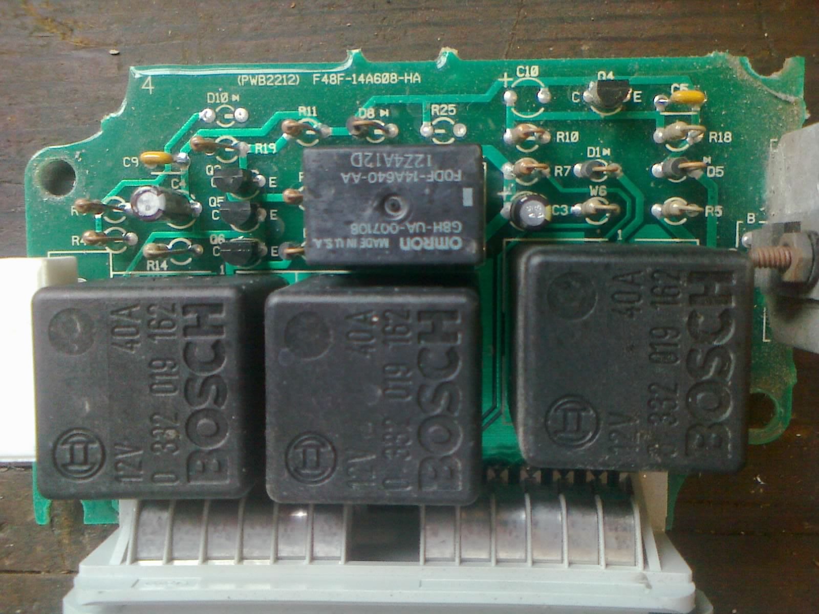
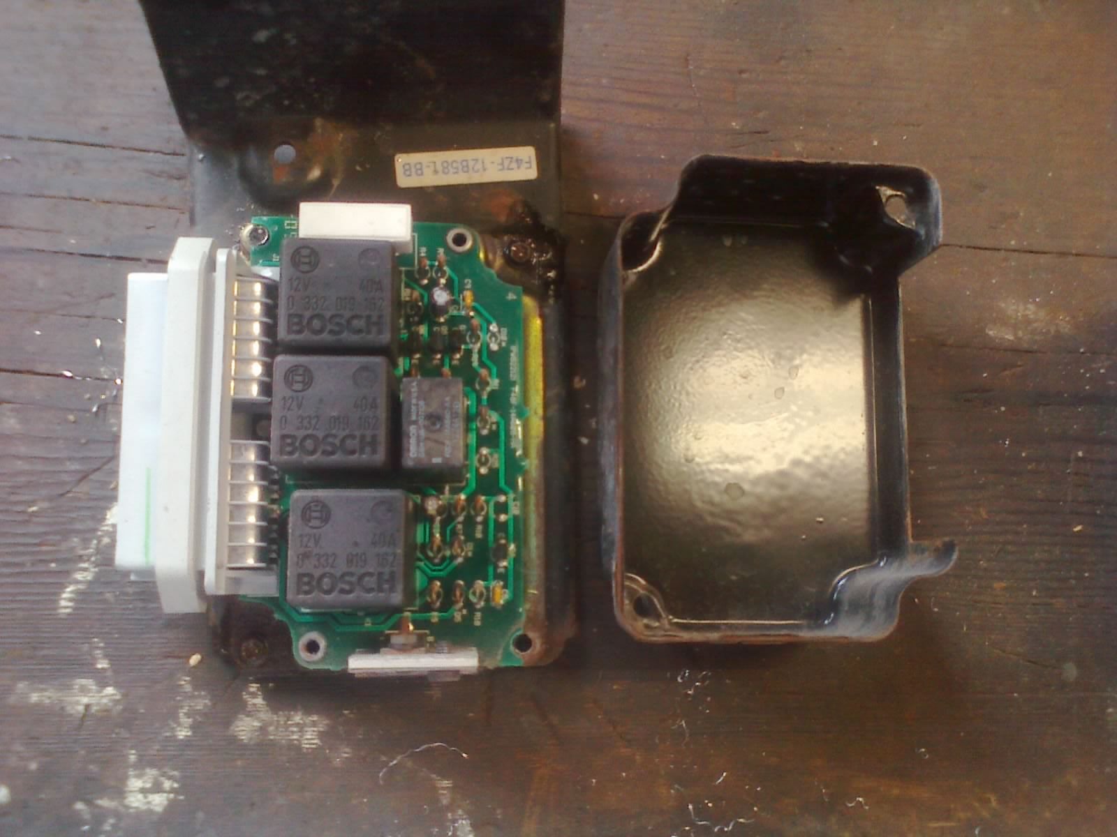
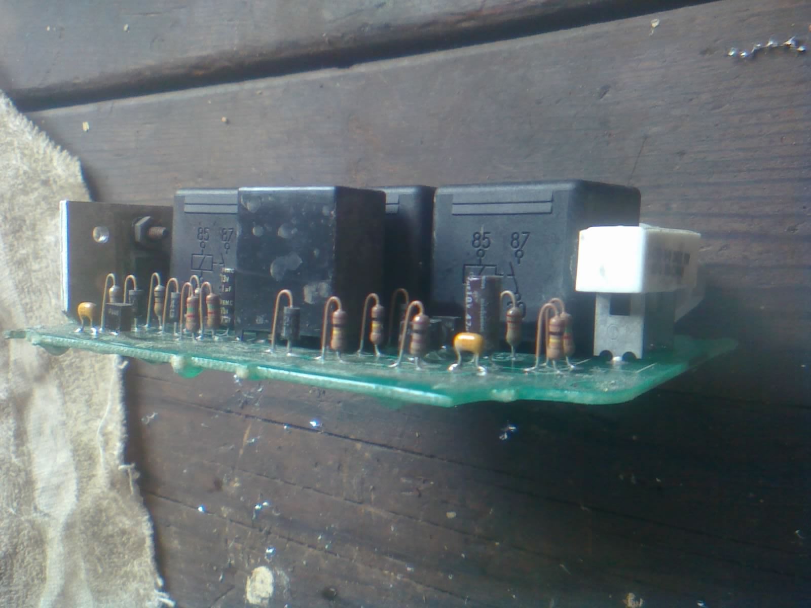
This is the Constant Control Relay Module (CCRM) out of my Mustang. Ford apparently didn’t want me to have access to certain relays, and instead made them part of this module, which runs about a hundred buckaroonies for a remanufactured unit.
That’s right, instead of swapping out a $5 relay, failure of any of the CCRM circuits means a triple-digit repair. Fuel pump relay go bad? Get a new CCRM. Radiator fan relay stop chooching? Fork over the cash. The CCRM also houses the PCM and AC relays, which are all soldered to the circuit board.
My car won’t run right now because I removed the CCRM. And I removed the CCRM because it won’t energize the AC clutch coil (I already performed the other necessary checks and narrowed it down to this module.) I did some research and found that drilling out a couple of rivets would give me access to the circuit board. That’s the easy part. The hard part is, I don’t see an AC relay!
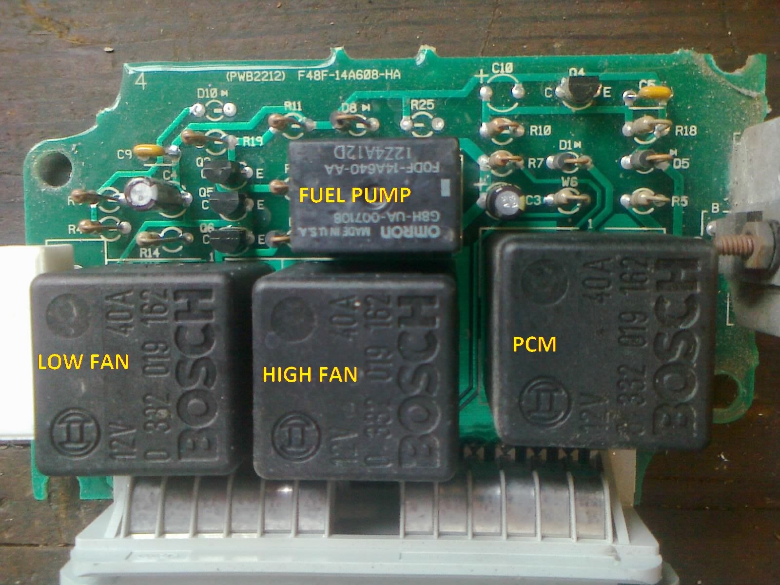
I identified the pins, traced some circuits, and found the PCM, fuel pump, high-speed fan, and low-speed fan relays. Mind you, the AC was working not long ago, so don’t go thinking that this is a CCRM out of a non-AC-equipped car. The AC circuit just doesn’t use a standard relay; it’s somehow controlled through the other little components.
There are NO obvious burn marks or breaks in the circuitry anywhere. Everything looks intact. I have no idea how the CCRM’s AC circuit functions, so it looks like I’m gonna have to test each little piece individually. I can check resistors, that’s not a big deal. And my meter has diode and capacitor modes, too. But I don’t know anything about transistors, much less how to test them.
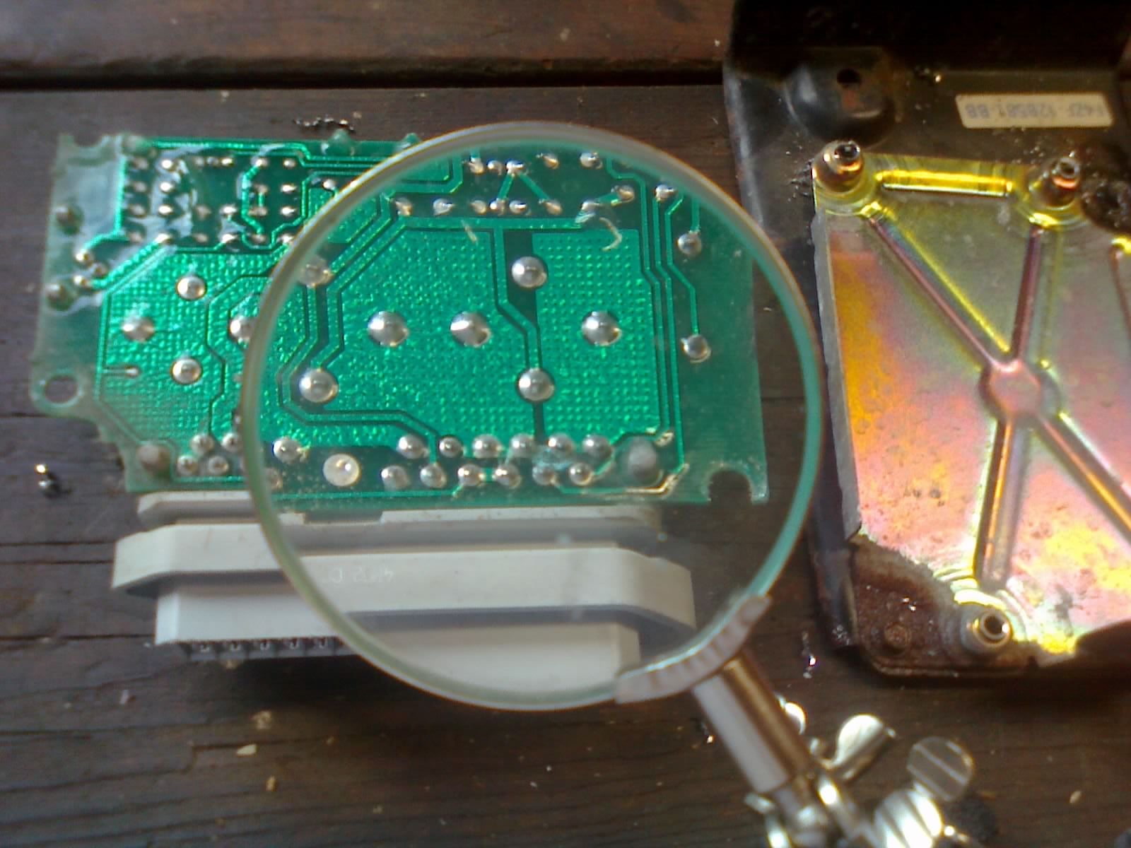
All I’ve managed to do so far is bench-test the relays (all good, as expected) and clean a tiny little bit of green corrosion I found around some of the main connector’s solder joints. (It was around the low-speed fan circuitry, which I believe has nothing to do with AC operation.)
I’m confident that If I put it back in now, the car will run, and keep itself from overheating. But I really want to fix my AC first, and I’d rather not buy a reman unit if I can get this one working instead.
Any ideas, Oppo?
 "E90M3" (e90m3)
08/05/2017 at 20:47, STARS: 2
I’m board.
Punny, very punny.
 "bhtooefr" (bhtooefr)
08/05/2017 at 20:51, STARS: 0
My suspicions would be, if the AC circuitry really isn’t shared with the relays...
Electrolytic capacitors are often failure-prone, and there’s two on the board (C3 and C4). They actually look OK, but they can fail invisibly, too.
Next, transistors could be the problem, the three at Q3/Q5/Q6 and the one on the other side at Q4.
Then, finally, I see diodes that could’ve failed as well, at D1, D5, and D8.
Resistors usually aren’t the problem.
 "Nibbles" (nibbles)
08/05/2017 at 20:51, STARS: 1
What year? Here is a CCRM with A/C control
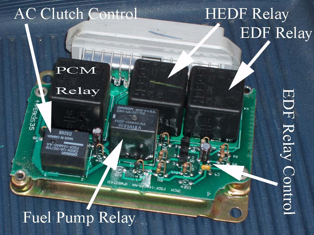
It doesn’t look like yours has the relay for A/C clutch control - the resistors in the same location may provide the same functionality (doubtful) or they could be passthrough to the actual relay located elsewhere.
"bhtooefr" (bhtooefr)
08/05/2017 at 20:53, STARS: 1
I doubt that resistors alone would do that, but there is a transistor and a diode in the region where that relay is...
"Nibbles" (nibbles)
08/05/2017 at 20:56, STARS: 2
Still some mighty tiny components to pump the requisite power
"Urambo Tauro" (urambotauro)
08/05/2017 at 20:56, STARS: 0
It’s a 1995 model. The Ford number on the board starts with “F4” which means that the design dates back to 1994, but I see “F5" in you pic there. Interesting.
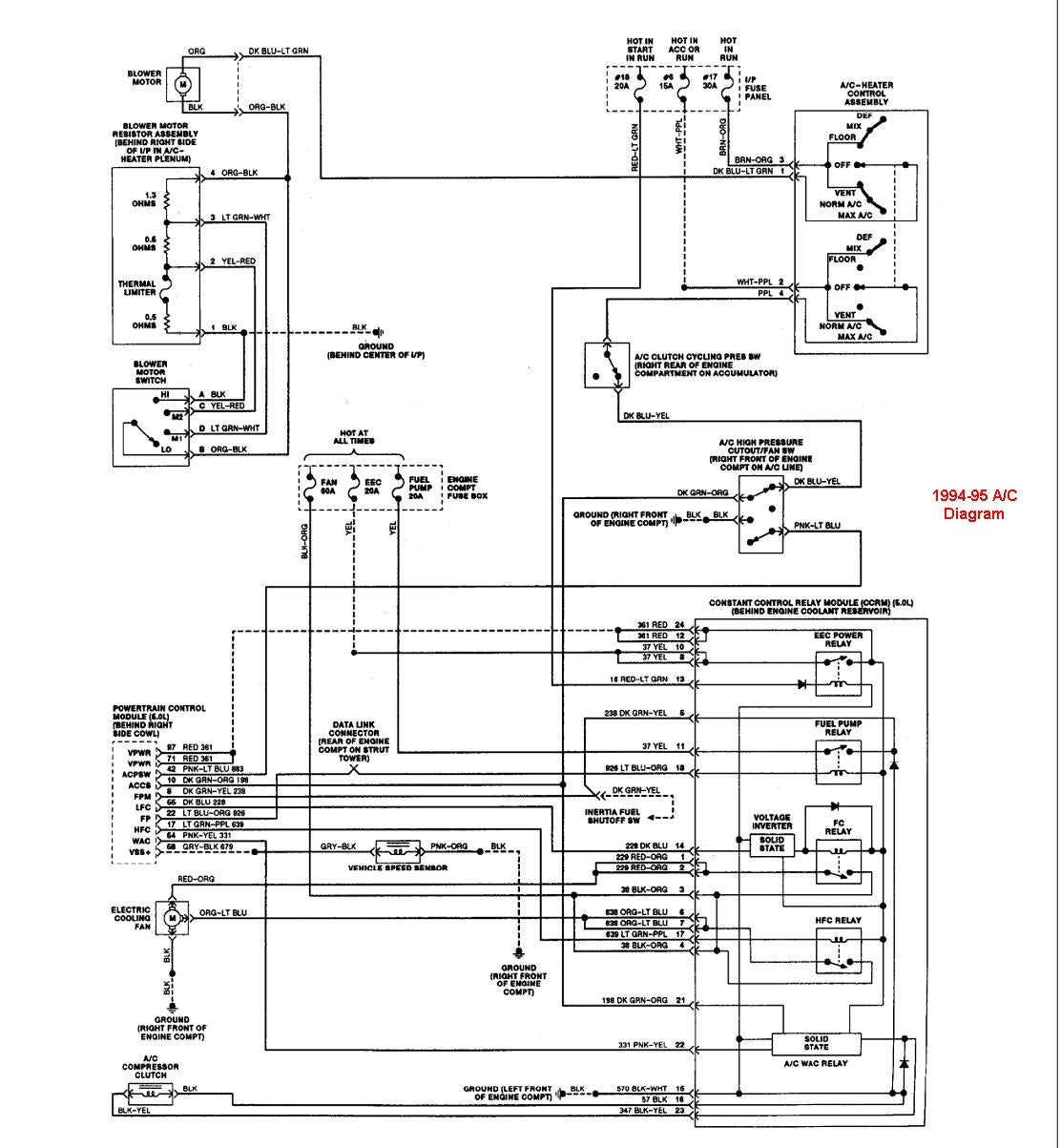
I found a simplified version of the CCRM circuits for this car, which shows that the AC “relay” is a “solid state” circuit, not a regular coil-type relay:
"Nibbles" (nibbles)
08/05/2017 at 20:58, STARS: 1
Then the resistors, transistor and diode may actually perform the control. Test those components and you may find your culprit
"Urambo Tauro" (urambotauro)
08/05/2017 at 20:59, STARS: 0
I think I’ll start checking capacitors and stuff tomorrow, if I can get a good look at what values to expect. Not sure how to check transistors, though...
 "MM54" (mm54mk2)
08/05/2017 at 21:01, STARS: 2
If you can read a part number on Q4 (such as “2n2222") it may be worth taking a shotgun approach and replacing that transistor and testing/replacing (if needed) the associated resistors. The transistor, if a standard one (which it should be) will run you a couple cents
"Urambo Tauro" (urambotauro)
08/05/2017 at 21:02, STARS: 1
I found a chart for resistor values. I’m gonna have to break out my magnifying glass again to read the transistors and diodes tomorrow. Not poking anything with a meter until I know what numbers to expect.
"Urambo Tauro" (urambotauro)
08/05/2017 at 21:03, STARS: 1
Man, I really wish the local Radio Shack hadn’t closed down!
"bhtooefr" (bhtooefr)
08/05/2017 at 21:06, STARS: 1
Capacitors can’t really be tested in circuit, so just replace them. Those will likely have a capacitance value (stick with that value) and a voltage (use at least that voltage) printed on them. Also, stick with 105 °C ratings for the replacements minimum .
Diodes, depending on the circuit, can be tested in circuit. One way, they should have low resistance, the other way, they should have infinite resistance.
Transistors... many multimeters actually have a transistor checker built in. Of course, those look like they’ll be cheap transistors to replace...
 "CTSenVy" (CTSenVy)
08/05/2017 at 21:27, STARS: 1
After looking at the pics and the wiring diagram, I would guess transistor Q4 is the part that’s switching on and off the ac clutch.
If you test the middle lead (the base) with the one next to the lead next E (for emitter) with the diode test it should act like a diode between those two points.
"Urambo Tauro" (urambotauro)
08/05/2017 at 21:40, STARS: 0
Ah, thanks! I’ll poke it tomorrow and see what it does.
"CTSenVy" (CTSenVy)
08/05/2017 at 21:52, STARS: 0
Good luck.
 "Mattbob" (mattbob)
08/05/2017 at 22:11, STARS: 1
Like MM54 said, it might be worth just replacing the transistors if you can read the part numbers. They are cheap, and you can’t really test them properly while they are in the circuit (unless you are sure about what else is in the circuit and what values you should get).
I did just notice what looks like a big mosfet attached to a heatsink on the one side of your board. This is probably what you are looking for, as those small transistors dont have near enough current carrying capacity to activate an AC clutch. I would focus here first!
 "TheTurbochargedSquirrel" (thatsquirrel)
08/05/2017 at 22:23, STARS: 1
Start with Q4. That’s your most likely suspect. After that I would check the diodes and resistors in that section of the board.
"Urambo Tauro" (urambotauro)
08/05/2017 at 22:41, STARS: 0
Oh, good call. Here, I did manage to get a slightly better picture of it:

The right-most terminal is labelled “E” on the board (hidden behind that PCM relay), which I understand to be for “emitter”. There is some very light surface rust on the screw that holds it to the aluminum plate, and there appears to be some sort of thin pad sandwiched between them.
That plate’s a heatsink? It gets fastened to the outer casing of the CCRM, which means that it probably touches chassis ground, too, through the mounting bracket. I also noticed what appears to be some greenish-greyish corrosion between the black body of the mosfet and the plate.
"Mattbob" (mattbob)
08/06/2017 at 16:22, STARS: 1
the plate acts as a heat sink, and the thin pad is probably a non conductive thermal interface material. I would say try to replace the mosfet, and clean up the board with some alcohol. It’s probably a $3 part if you are buying just one. Also fun fact, the picture next to my name is a mosfet diagram.