 by "BiTurbo228 - Dr Frankenstein of Spitfires" (biturbo228)
Published 04/10/2017 at 15:55
by "BiTurbo228 - Dr Frankenstein of Spitfires" (biturbo228)
Published 04/10/2017 at 15:55
Tags: spit6
STARS: 3
I’ve re-drilled the holes for the vertical link to take into account the added length of the hub and brake drum onto the end of the vertical link, measured the shock travel, and drilled a load of more holes for popular aftermarket wishbone locations :) at this point, I realised that I don’t own a protractor. Bugger. To the shops tomorrow!
 "RamblinRover Luxury-Yacht" (ramblininexile)
04/10/2017 at 16:05, STARS: 1
Your first instinct on this was almost surely correct, to have the lower link as low as you can get away with on the inside. Not only for the camber change being better, but the fact that the roll center is so high for a sharp angle. That being said, there might be some reason for a high roll center in back, just can’t say what - or there might be advantages to a Herald-like sharp tuck of the inner wheel to counterbalance that. Can’t say. :)
The real saboteur in the whole affair is that the spring on top makes for such a bloody long control arm. Exactly opposite to recognized solid practice.
"BiTurbo228 - Dr Frankenstein of Spitfires" (biturbo228)
04/10/2017 at 16:50, STARS: 0
Yeah I think the Triumph engineers were bloody clever getting camber change in the right direction at least by angling the short lower wishbone, but it does have a detrimental effect on the roll centre.
One of my future steps is to calculate the roll centre of the front suspension so I can make sure that my proposed wishbone design had a roll centre just a tad higher than the front (not worked out why that’s a good idea yet, just know that it’s accepted practice), but lower than the stock one.
I suppose sharp camber change would actually suit a high-roll car quite well...
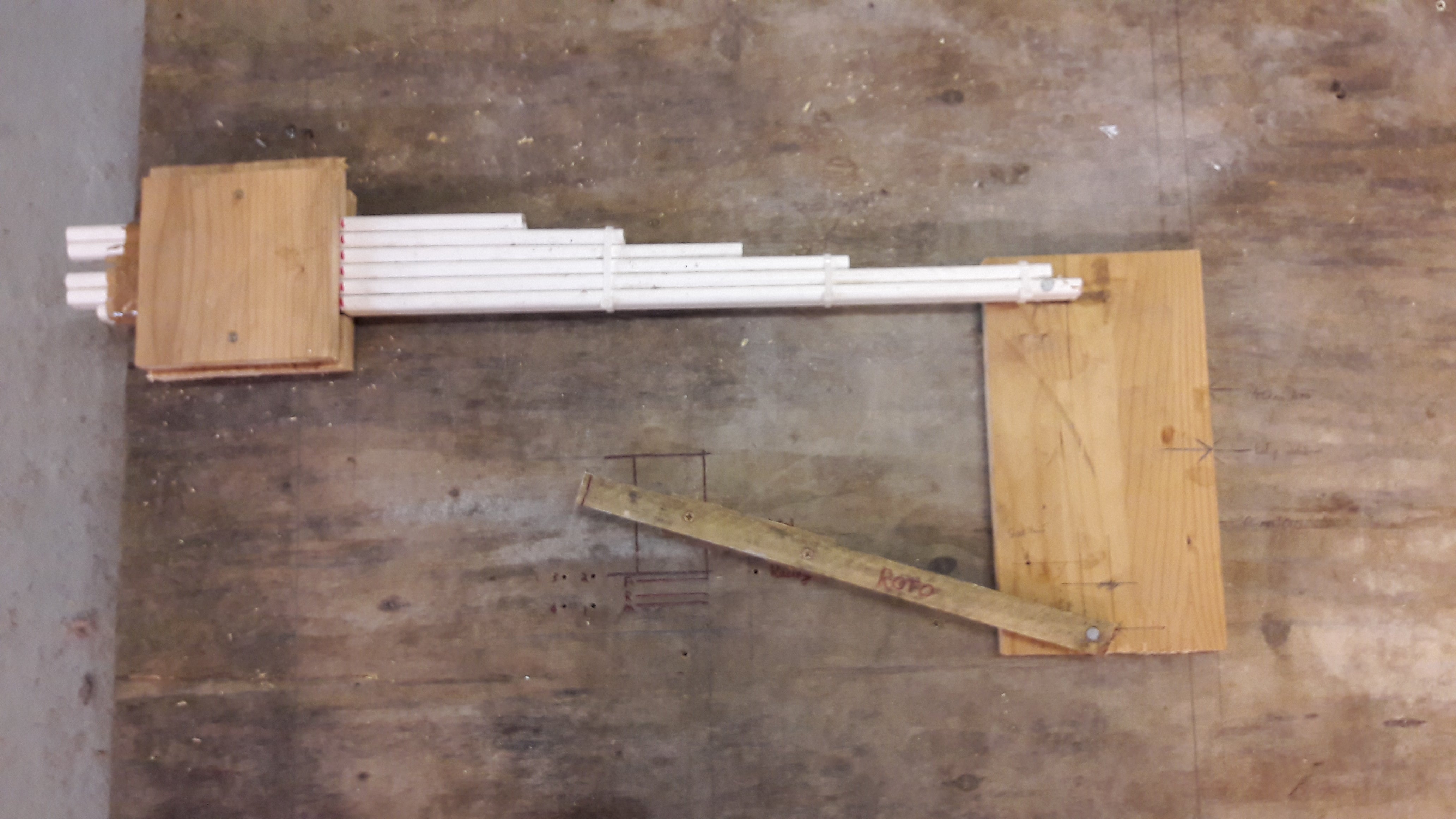
As for the leaf being a really long upper link it’s actually nowhere near as bad as it initially seems. As it’s sprung, it doesn’t behave the same as a solid link and actually curves inwards as the suspension moves (as this shows):
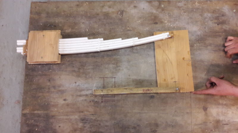
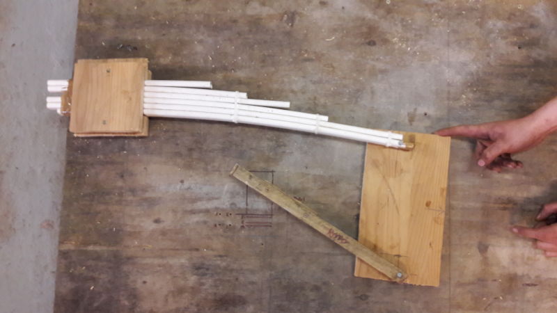
Now I haven’t tested any of it yet, but the chap I’ve cribbed this idea from worked it out in practice (on his car, rather than on his model) that if you mount a lower wishbone dead level just under the chassis it actually produces a near-zero camber change for most of the suspension travel which goes against what you’d expect for such a long upper control arm.
Also, by the looks of things (again, need to measure), because of how the leaf is constructed it actually shortens more in bump than in droop, meaning you get a little more negative camber compared to the positive camber on droop which is what you want really.
It’s actually rather clever by the Triumph engineers, provided it was intentional!
"RamblinRover Luxury-Yacht" (ramblininexile)
04/10/2017 at 17:12, STARS: 0
Shortening more in bump than in droop would be the case any time you had the spring at rest as an arc open upward, or very nearly. I’m not sure I credit the Triumph engineers with anything other than using minimal packaging, but there it is - not really a *surprise*, as such, and something they *could have* expected.
Nearly twice the rate of change downward in length for a change from a 5 degree upward incident spring to 10 degrees for each additional degree, even without curvature (tangent).
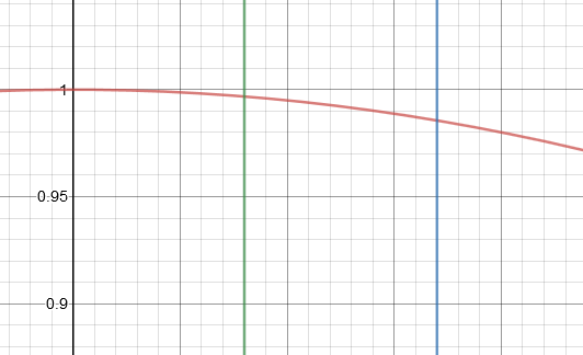
Total with curvature would be something like cos(theta) - k*sin^2(theta) or something of that nature - may have it all wrong, but if that’s right, something like this:
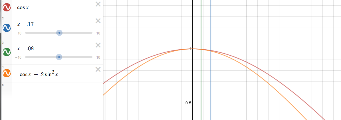
Very rapid rate of length change per degree where it matters.
The short arm nearly level isn’t surprising, because it stands to reason that the short arm experiences the greatest total length change - because it moves through a much greater angle. It would be fairly standard to leave the shortest arm (as it’s the controlling element) as close to flat as possible for the flattest camber change, because you’re pinning its angle range down fairly tight to a plus/minus either side of zero even for big movements.
The two biggest reasons a Shelby drop is a good with a Mustang first-gen suspension are lowering the roll center and winding up with a shorter arm closer to level (actually a thin hair on the other side from stock).
 "davedave1111" (davedave1111)
04/11/2017 at 04:47, STARS: 0
“at this point, I realised that I don’t own a protractor. Bugger. To the shops tomorrow!”
Wait,
that’s
where you draw the line? I don’t understand the geometry here, but even I can make a protractor.
"BiTurbo228 - Dr Frankenstein of Spitfires" (biturbo228)
04/11/2017 at 04:56, STARS: 0
Now that you point it out that is a little ridiculous ;)
Context was that at the point I realised I didn’t own a protractor it was dinner time (we eat late) and I can pick one up on my lunch break today and get cracking as soon as I get home :)
"davedave1111" (davedave1111)
04/11/2017 at 05:16, STARS: 0
Well, stopping for grub is acceptable. But you can mark out a 360 degree protractor using just a pair of compasses and a straight edge.
Talking of idealized constructions, do you have any movement in other planes to worry about? Strikes me that a leaf spring wouldn’t provide the most accurate fore-aft control. I’d have thought you’d get less play with a shorter lower arm, although whether that’s enough to make a difference I haven’t a clue.
"BiTurbo228 - Dr Frankenstein of Spitfires" (biturbo228)
04/11/2017 at 05:42, STARS: 0
If I can’t find a suitable one today then I’ll definitely do that :)
Oddly the leaf spring isn’t too bad for fore-aft control as it’s a lot wider horizontally so works quite nicely. It’s not exactly an A-Arm, but it’ll do.
On the stock suspension it’s got a tie rod running forwards to control fore-aft movement, but that introduces bump-steer (it basically mimics a semi-trailing arm for bump-steer characteristics). On mine I’ll have an A-arm as widely spaced as I can get it which should hold it pretty damn steady. There might be some issues with the whole thing rotating slightly around the axle axis, but I’ll have to test that using a video on the car (or a big bar bolted to the vertical link to try and twist the suspension). If that it a problem, I was thinking of running a link dead straight forwards onto the chassis from the leaf spring mount (although I’d like to avoid that if possible, as the arc of that will push the whole thing backwards and forwards as it compresses).
That lot probably makes no sense at all! It’s bloody difficult to describe suspension stuff without doodles and diagrams...
"davedave1111" (davedave1111)
04/11/2017 at 07:22, STARS: 0
It seems to me to make some sense, but I quite possibly misunderstood something. I’m terrible at visualising dynamic geometry.
I was mainly wondering whether the ideal best solution is actually the real-world best once you take into account stiffness and weight of the control arms. If you have to beef up the a-arm by a few kilos to hold the wheel in the right position, then you’d end up with - I’m guessing here - suspension that was less responsive (unsprung weight), but predictable?
"BiTurbo228 - Dr Frankenstein of Spitfires" (biturbo228)
04/11/2017 at 09:08, STARS: 0
Ah I see. Yeah the total unsprung mass is a definite concern, but based on my previous iteration of wishbones I’ve got a ton of headroom before it starts to get even close to the stock setup.
The stock rotoflex wishbone and tie rod I’ve weighed at 6.8k per side, whereas my tubular lower a-arm weighed a svelte 1.3kg per side. The way I’d get additional location is by running a new rod to locate things, rather than beefing up the existing ones. With the tube I’m using that additional rod will be max 1kg so I’d still be 4.5kg up :)
It’s also helped slightly by the fact that another chap has pioneered a similar sort of lower wishbone a-arm and hasn’t reported any issues with it (and I’m using more expensive/stronger tube than him). I’m planning on doing some GoPro footage of it in action though to identify if there’s any weak points :)
"BiTurbo228 - Dr Frankenstein of Spitfires" (biturbo228)
04/11/2017 at 11:07, STARS: 0
Yeah the clever part was that by angling the short arm rather than making it level, you get negative camber on bump where otherwise you wouldn’t with such a short lower arm (although that is at the trade-off of sharply increasing positive camber on droop).
Yeah I wouldn’t credit the engineers with anything other than packaging and reducing parts costs, but it’s a neat thing if they did think of it :)
"davedave1111" (davedave1111)
04/11/2017 at 13:45, STARS: 0
“I’ve got a ton of headroom before it starts to get even close to the stock setup”
I expect you do - but what about when comparing to optimal solutions?
I mean, obviously you wouldn’t add 20kg for a 0.1% better camber curve. And you’d happily add 1kg for a 100% improvement. But what’s optimal? Best wheel location and a few extra kg, or slightly compromised wheel location and a few kg less? Or is it actually not really a trade-off between the two at all?