 by "BiTurbo228 - Dr Frankenstein of Spitfires" (biturbo228)
Published 04/03/2017 at 09:40
by "BiTurbo228 - Dr Frankenstein of Spitfires" (biturbo228)
Published 04/03/2017 at 09:40
Tags: Spit6
STARS: 7
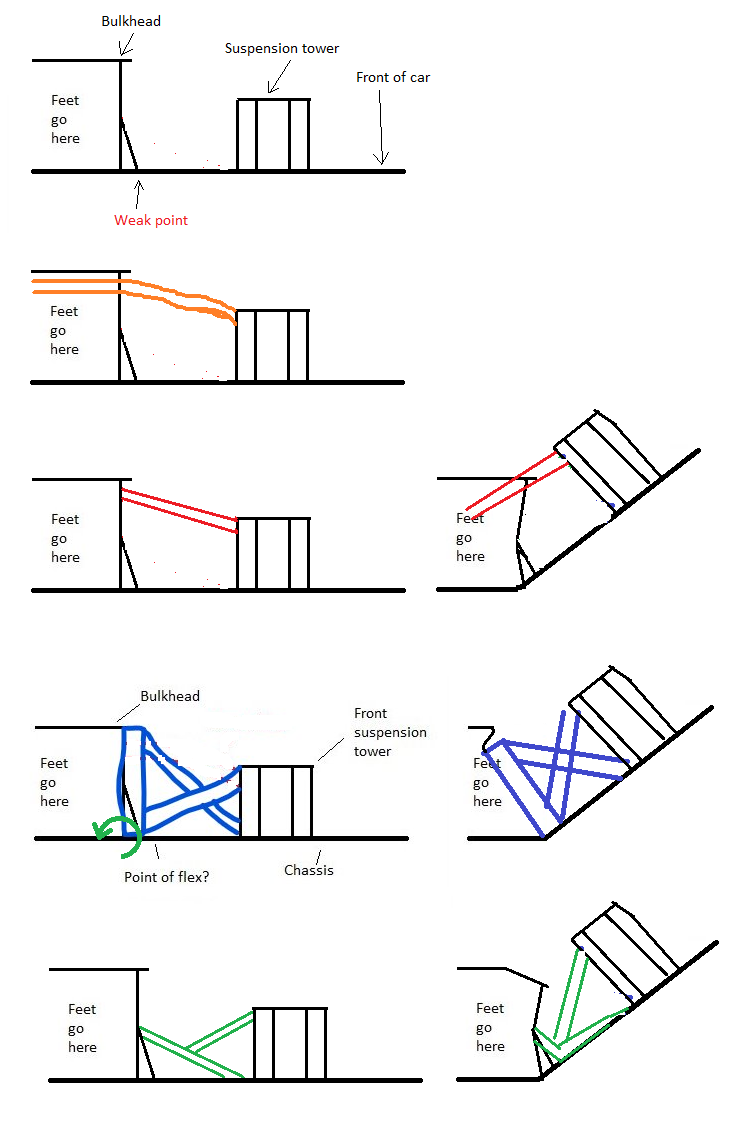
I have now finished boxing in the Spit’s bodyshell to the chassis which will improve the chassis stiffness a lot (by an estimated 37% over standard just from the additional width added to the chassis rails, excluding the sills, roof structure and roll hoop which some seriously dodgy maths aside is pretty impressive!). However, there’s still a point in the chassis just before the front bulkhead where it’s only the chassis rails providing stiffness which just won’t do ( see first terrible MS Paint doodle, which is the front section of car in profile view ).
As a bit of a recap, here’s my thought process:
Most people concerned with stiffness are racers so simply extend their cage through the bulkhead to meet the suspension towers ( see second crayon scribble ). As I don’t want a full cage, just running a tube from the suspension towers to the bulkhead would work too. Unfortunately, in the event of a crash that would result in a weld-hardened spar of tube punching through the flimsy bulkhead and spearing my feet ( see third child’s art project ).
The next option was to construct an x-frame between the suspension tower and a reinforced bulkhead. Unfortunately again, without reinforcing the rest of the body structure behind it (which is tight on legroom anyway), I’m fairly certain the whole thing would just pivot backwards and crush my feet instead of spearing them :S ( see fourth Tate Modern exhibition ).
So, with liberal application of what is generously described as ‘brainpower’, I came up with the final Impressionist masterpiece. The lower brace (2mm wall tube) is attached to a beefed up existing body mounting bracket on the bulkhead and a point on the chassis. A thicker-wall tube is then placed from the centre of that brace to locate the suspension tower. In the event of a crash, the 2mm wall tube should bend where it meets the thicker tube, preventing any premature podiatry appointments.
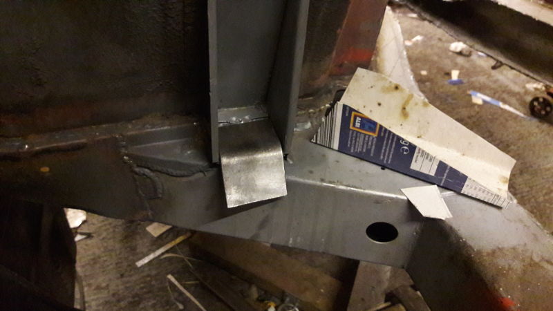
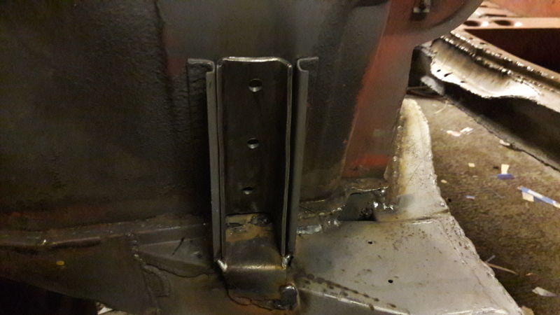
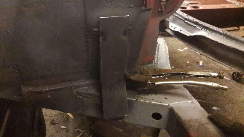
The first step in this plan not to cripple myself was to make doubly damn certain that bracket on the bulkhead wasn’t going anywhere in the event of a crash. Here it is in all it’s 2mm steel glory (down at the bottom):
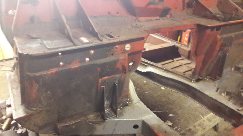
First step is to chip off all of the underseal gunk and make sure the steel behind it is solid.
So far so good. Then onto some Binky-esque CAD (Cardboard Aided Design) templates.
First plate made from 3mm steel was easy enough. Simple cut, bend roughly into shape, tack one end, beat with a hammer until it’s the shape it needs to be and then weld in fully.
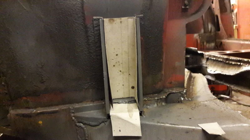
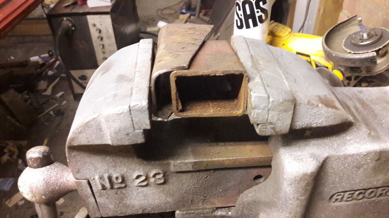
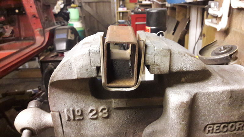
The next one required a cup of tea and some thinking time. I could bend it roughly to shape with some muscle and a vice, but it wasn’t quite as square as I’d hoped. Luckily, a piece of spare box section I had seemed the right shape so I used the vice to press it into a better shape.
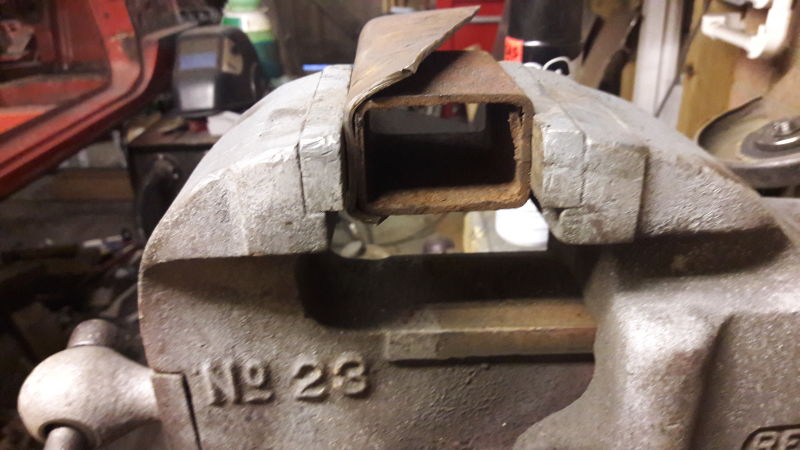
A bit more hammering and a bit more pressing and voila!
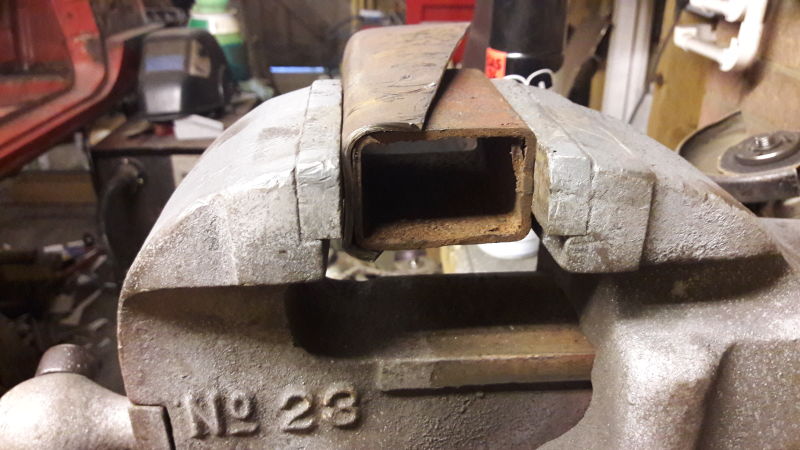
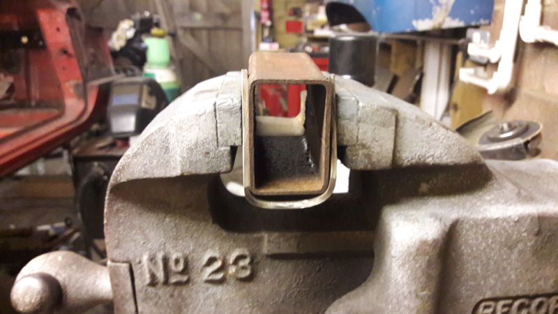
Very neat :)
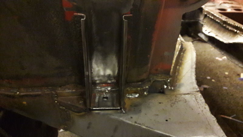
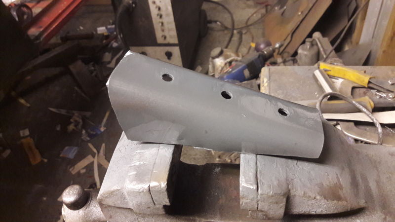
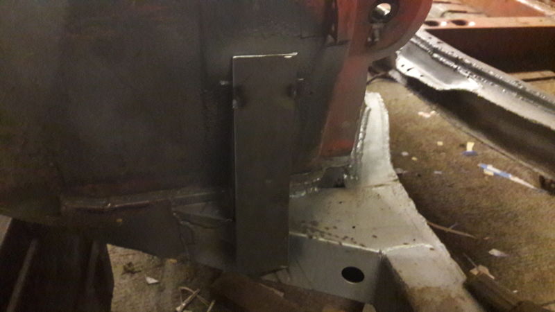
Drill some big holes for some beefy plug-welds and spray with some weld-through primer in an attempt to rust-protect the back slightly...
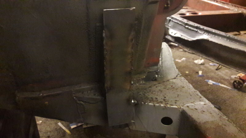
...and tack in place.
This as proof that every now and again I can lay down a weld that looks bang-on ;)
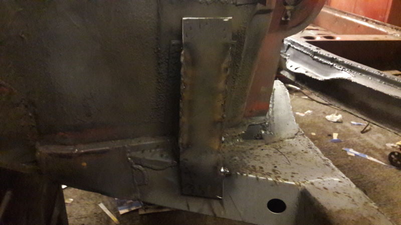
More primer and a new plate over the top.
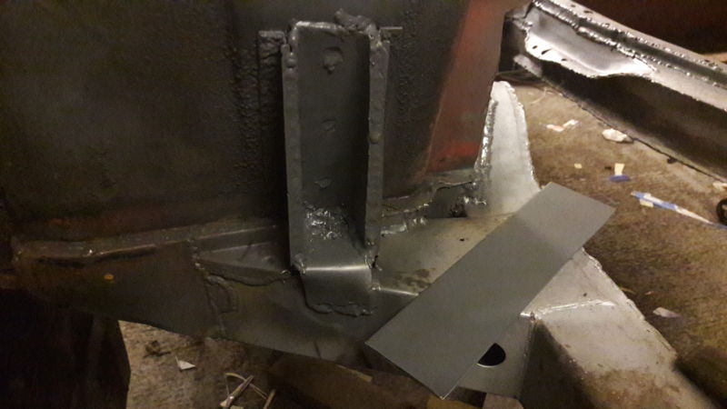
Tacked in place...
...hammered roughly to shape...
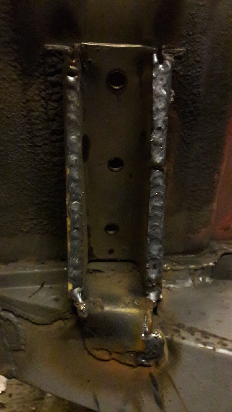
...mostly welded...
...some more hammering...
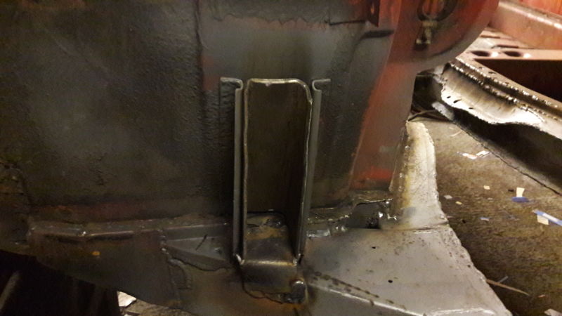
...and done! Except the fully welding of the bit at the bottom which I forgot to take a pic of...
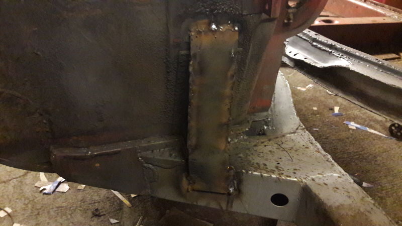
Hopefully that should be a proper strong-point for the tubing to mount to, and the double-thickness of 3mm steel welded to the chassis extension should prevent it tearing off there and pivoting backwards. I’ve done the other side in an identical manner as well and one more job ticked off the list :)
Welding-wise, I’ve got one more plate tying the hardtop to the roll hoop, welding the roll hoop feet fully to the bodyshell, re-locating the rear suspension mounts inboard of the chassis for better geometry and ground clearance, and the brace structure explained at the start of this post.
Then I might be able to do something that’s not welding! God forbid!
 "Shoop" (shoopdawoop993)
04/03/2017 at 09:47, STARS: 1
I wish I could weld.
 "CalzoneGolem" (calzonegolem)
04/03/2017 at 09:49, STARS: 0
Keep on welding you crazy fool! Keep on welding for all of us!
 "diplodicus" (diplodicus)
04/03/2017 at 09:54, STARS: 0
Me too, I have a welder available to me. So I really need to just stop being lazy and start welding things.
"BiTurbo228 - Dr Frankenstein of Spitfires" (biturbo228)
04/03/2017 at 09:57, STARS: 0
MIG welding’s actually relatively simple :) just grab a welder, some shielding gas, some welding wire, a welding mask and some scrap steel and start sticking stuff together. You’ll pick up the technique after a couple of tutorial videos and giving it a go yourself :)
Takes a long time to get stuff looking consistently nice, but not as long as you’d think to just stick one piece of metal to another :)
"BiTurbo228 - Dr Frankenstein of Spitfires" (biturbo228)
04/03/2017 at 10:02, STARS: 2
Haha i’ve got enough welding to go around between this, two other spits, the MG Baja and whatever other sills and battery trays disintegrate on any otger car that comes my way :S
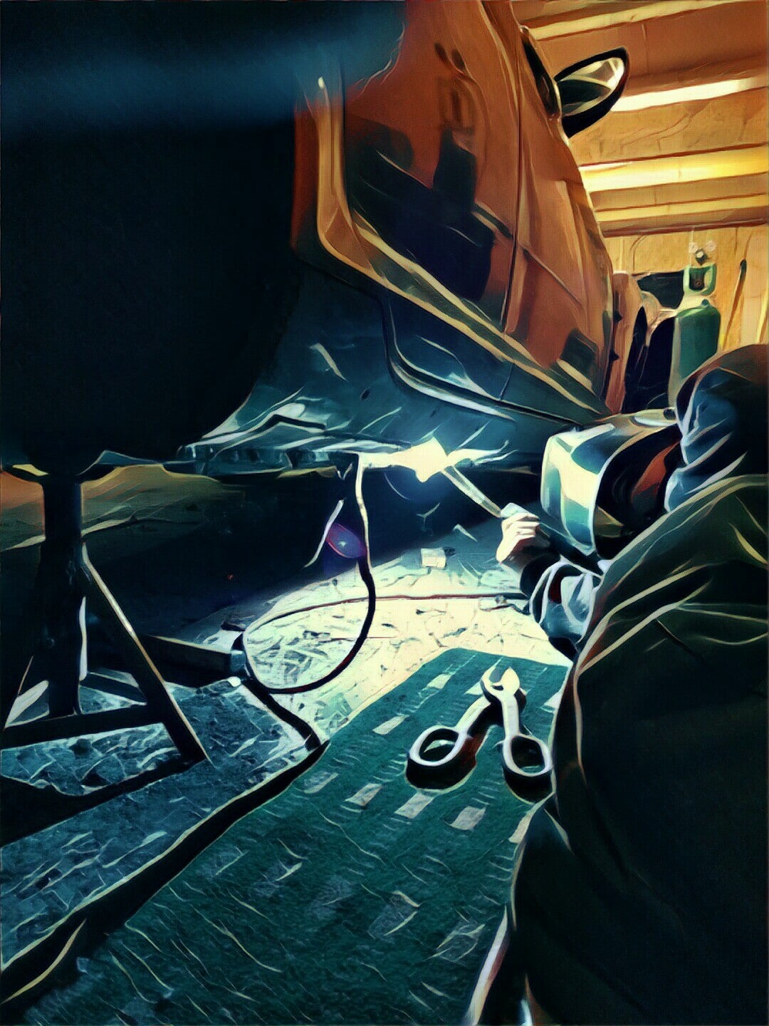
Did get this cool pic of me fixing my mate’s RX8 last-minute before Europpomeet though :)
 "RamblinRover Luxury-Yacht" (ramblininexile)
04/03/2017 at 10:24, STARS: 0
Very nice. I seem to recall trying to push you in that sort of direction, but the expansion of the existing frame bracket is, I believe, a new innovation.
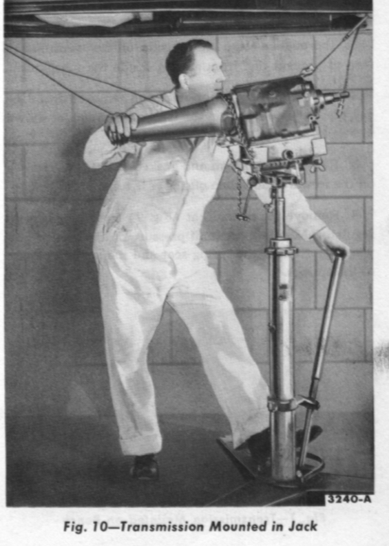
I spent Saturday pulling the trans out of the Galaxie, performing a front pump seal replace, opening up, inspecting a couple of parts, cleaning, and putting back in. Looked something like this bit from the ‘58 manual:
Also, have most likely eliminated lingering leaks from the hose replacements, greased the driveshaft (shall need new u-joints soon), and replaced the gear oil in the diff - most likely never been changed in 98,000 miles - black as a coal mine. Fortunately, the legendary Ford 9-inch, so likely not bothered.
I’m going to try today to sort out the wacky suspension cranks, replace their bushings, and put in shocks, with a soupcon of “find out if the gas sender is working”.
"BiTurbo228 - Dr Frankenstein of Spitfires" (biturbo228)
04/03/2017 at 10:32, STARS: 0
Yeah it was definitely developed with considerable input from RamblinRover ;)
You’ve been busy! Only a matter of time til the big ol’ girl’s on the road :)
"RamblinRover Luxury-Yacht" (ramblininexile)
04/03/2017 at 10:40, STARS: 1
It’s been on the road! It just keeps coming back off it for a day at a time due to one or more aspects being rubbish. I’ve had it up to sixty now, and it’s a proper sailing ship - roaring along with whuffing from the exhaust crack and “off” carburetor tune - great fun.
One final thing I’ll be trying to sort - the rear brake flex line. The rear cylinders have been replaced at some point, but the rear flex has crumbled and clogged inside, so I don’t have more than a suggestion of rear brake...
"BiTurbo228 - Dr Frankenstein of Spitfires" (biturbo228)
04/03/2017 at 10:47, STARS: 0
Nice! :)
I’m half expecting Ford to have designed it that under heavy braking the rear wheels pivot outwards to act as an airbrake or something...
Honestly I’m still marveling at the bellcrank front wishbone joint. Actually, could you actually make it workable if it’s damped properly? Something like attach a shock of some sort from there to the body on a balljoint so control the movement somewhat so you don’t have such a strong swing from one side to the other?
"RamblinRover Luxury-Yacht" (ramblininexile)
04/03/2017 at 10:59, STARS: 0
I’m looking into ways to build a brace that will work like the original Ford one except for allowing a little more crank movement. The original style alteration was a flat steel bar (nearly complete immobilization), the Moog aftermarket rig was less than complete with some rubber bushing damping (but no linking left to right), and the adjustable one now on the market uses heim joints - permitting some crank movement but lacking in damping...
There’s a bit of damping in the stock setup with the bushing clamped to the crank, but it’s rubbish because the whole thing just pivots on the crank instead of twisting the bushing.
My suspicion is that the best invention will be a bar with a sleeve through the hole - to stabilize the bushing to the crank, allow for the brace to pivot a bit, and manage all the damping with rubber washers. Like this:
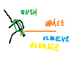
There’s at least a 5/8" spare amount of thread room on the crank for backing its nut off, so this should be workable.
"BiTurbo228 - Dr Frankenstein of Spitfires" (biturbo228)
04/03/2017 at 19:28, STARS: 0
Ah I think I see :) so solid bar with thick rubber bushes on each end to provide more compliance than the Ford one, but still link the two together. Sounds like it might do the trick, but I’m having difficulty wrapping my internal physics model around how that would all play out under different suspension loads :S I’ll get there, but it’ll take some significant time sitting there with my tongue sticking out...
 "davedave1111" (davedave1111)
04/04/2017 at 05:55, STARS: 0
“Unfortunately, in the event of a crash that would result in a weld-hardened spar of tube punching through the flimsy bulkhead and spearing my feet”
So don’t crash.